 |
am2zzw00000899
SECURITY LIGHT: 11, DTC: B10D9:87/P1260:00 [IMMOBILIZER SYSTEM (KEYLESS ENTRY SYSTEM)]
id0902e5353000
|
DTC |
Security light flashing pattern |
11 |
No detected communication with coil antenna. |
|
|---|---|---|---|---|
|
M-MDS display |
Instrument cluster |
B10D9:87 |
||
|
PCM |
P1260:00 |
|||
|
POSSIBLE CAUSE
|
• METER 10 A fuse malfunction
• Coil antenna malfunction
• Instrument cluster malfunction
• Related wiring harnesses malfunction
|
|||
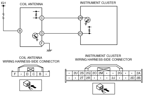
System wiring diagram
am2zzw00000899
|
Diagnostic Procedure
|
Step |
Inspection |
Action |
|
|---|---|---|---|
|
1
|
VERIFY COIL ANTENNA CORRECTLY INSTALLED
• Verify the installation condition of the coil antenna.
• Is the coil antenna correctly installed? (Is the connector pulled out?)
|
Yes
|
Go to the next step.
|
|
No
|
Install the coil antenna correctly, then go to the next step.
|
||
|
2
|
FUSE INSPECTION
• Turn the ignition switch to the LOCK position.
• Disconnect the negative battery cable.
• Remove the METER 10 A fuse.
• Is the fuse normal?
|
Yes
|
Go to the next step.
|
|
No
|
Replace the fuse, then go to Step 9.
|
||
|
3
|
INSPECT COIL ANTENNA POWER SUPPLY
• Disconnect the coil antenna connector.
• Connect the negative battery cable.
• Turn the ignition switch to the ON position.
• Measure the voltage at coil antenna connector terminal B.
|
Yes
|
Go to the next step.
|
|
No
|
Repair or replace the wiring harness, then go to Step 9.
|
||
|
4
|
INSPECT WIRING HARNESS BETWEEN COIL ANTENNA AND GROUND
• Turn the ignition switch to the LOCK position.
• Disconnect the negative battery cable.
• Measure the continuity of the wiring harness between coil antenna connector terminal C and ground.
• Is there continuity?
|
Yes
|
Go to the next step.
|
|
No
|
Repair or replace the wiring harness, then go to Step 9.
|
||
|
5
|
INSPECT COMMUNICATION CIRCUIT (INPUT) FOR CONTINUITY
• Disconnect the instrument cluster connector.
• Measure the continuity of the wiring harness between coil antenna connector terminal C and instrument cluster connector terminal 2M.
• Is there continuity?
|
Yes
|
Go to the next step.
|
|
No
|
Repair or replace the wiring harness between the coil antenna and the instrument cluster, then go to Step 9.
|
||
|
6
|
INSPECT COMMUNICATION CIRCUIT (OUTPUT) FOR CONTINUITY
• Measure the continuity of the wiring harness between coil antenna connector terminal D and instrument cluster connector terminal 2Q.
• Is there continuity?
|
Yes
|
Go to the next step.
|
|
No
|
Repair or replace the wiring harness between the coil antenna and the instrument cluster, then go to Step 9.
|
||
|
7
|
INSPECT COIL ANTENNA INPUT SIGNAL CIRCUIT
• Connect the coil antenna connector.
• Connect the negative battery cable.
• Turn the ignition switch to the ON position.
• Measure the voltage at coil antenna connector terminal C.
|
Yes
|
Go to the next step.
|
|
No
|
• Replacing the coil antenna.
• Go to Step 9.
|
||
|
8
|
INSPECT COMMUNICATION CIRCUIT (OUTPUT) FOR CONTINUITY
• Measure the continuity of the wiring harness between coil antenna connector terminal ground.
• Is there continuity?
|
Yes
|
Go to the next step.
|
|
No
|
• Replacing the coil antenna.
• Go to the next step.
|
||
|
9
|
VERIFY AFTER REPAIR
• Turn the ignition switch to the LOCK position.
• Disconnect the negative battery cable.
• Reconnect the disconnected connectors.
• Connect the negative battery cable.
• Clear the DTC.
• Verify if any DTCs are displayed.
• Are DTCs output again?
|
Yes
|
• Replace the instrument cluster and program the immobilizer system-related parts.
• Go to the next step.
|
|
No
|
Go to the next step.
|
||
|
10
|
VERIFY THAT NO OTHER DTCs ARE PRESENT
• Verify if other DTCs are displayed.
• Are any other DTCs output?
|
Yes
|
Perform the corresponding DTC inspection.
|
|
No
|
DTC troubleshooting completed.
|
||