 |
am2zzw00002915
INSTRUMENT CLUSTER INSPECTION [MZ-CD 1.4 DI Turbo, MZ-CD 1.6 (Y6)]
id0922004964j5
Speedometer
1. Adjust the tire pressure to the specification.
2. Using a speedometer tester, verify that the tester reading is as indicated in the table.
European (L.H.D. U.K.) specs.
|
Speedometer tester indication (km/h) |
Allowable range (km/h) |
|---|---|
|
20
|
20—25
|
|
40
|
41—45
|
|
60
|
61—66
|
|
80
|
82—87
|
|
100
|
102—108
|
|
120
|
123—129
|
|
140
|
143—150
|
U.K. specs.
|
Speedometer tester indication (mph) |
Allowable range (mph) |
|---|---|
|
10
|
10—13
|
|
20
|
20—23
|
|
30
|
30—34
|
|
40
|
41—44
|
|
50
|
51—55
|
|
60
|
61—66
|
|
70
|
72—76
|
|
80
|
82—87
|
Tachometer
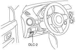
1. Connect the M-MDS to the DLC-2.
am2zzw00002915
|
2. After vehicle identification, the following can be selected from the M-MDS initialization screen.
3. Select “TACHOMTR” from PID/DATA Monitor Table.
4. Verify the monitored value according to the directions on the screen.
Fuel gauge
1. Connect the M-MDS to the DLC-2.
am2zzw00002915
|
2. After vehicle identification, the following can be selected from the M-MDS initialization screen.
3. Verify that all the segments are displayed using “LCD_SEG”.
4. Disconnect the negative battery cable.
5. Remove the rear seat cushion. (See REAR SEAT CUSHION REMOVAL/INSTALLATION.)
6. Remove the service hole cover.
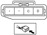
7. Disconnect the fuel gauge sender unit connector.
8. Connect the negative battery cable.
9. Connect the SST (Fuel and thermometer checker) to fuel gauge sender unit connector terminals C and D.
am2zzw00002916
|
10. Verify the fuel gauge reading is as indicated in the table using the SST (Fuel and thermometer checker).
|
Fuel gauge indication (instrument cluster) |
Resistance of SST (Fuel and thermometer checker) (ohm) |
|---|---|
 |
Approx. 60 or less
|
 |
Approx. 61—92
|
 |
Approx. 93—127
|
 |
Approx. 128—159
|
 |
Approx. 160—191
|
 |
Approx. 192—225
|
 |
Approx. 226—260
|
 |
Approx. 261—277
|
 |
Approx. 278—293
|
 |
Approx. 294 or more
|