 |
am2zzn00000582
CAN SYSTEM DESCRIPTION
id094000101000
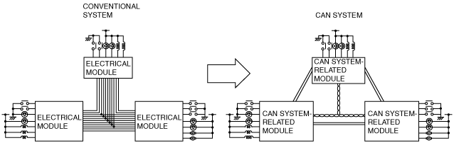
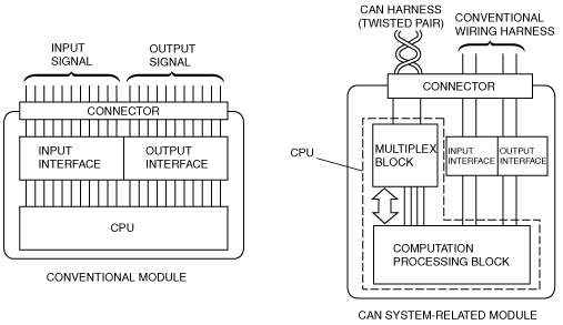
Mechanism of CAN System-Related Module
|
Component |
Function |
|
|---|---|---|
|
Electrical circuit
|
Supplies power to CPU and vicinity, and to input/output interface.
|
|
|
CPU
|
Computation processing block
|
Control function has been expanded, and when transmission is necessary, transmitted data is stored in a multiplex block. If a multiplex block receives a request to read stored data, transmitted data is read from the multiplex block.
|
|
Multiplex block
|
Transmits data received from bus line to computation processing block. In addition, sends transmitted data stored from computation processing block to bus line.
|
|
|
Input/Output interface
|
Electrically converts information signals from switches to, be input to CPU, and signals output from CPU for operating actuator or indicator lights.
|
|
am2zzn00000582
|
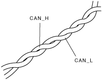
Twisted Pair
am2zzn00000583
|
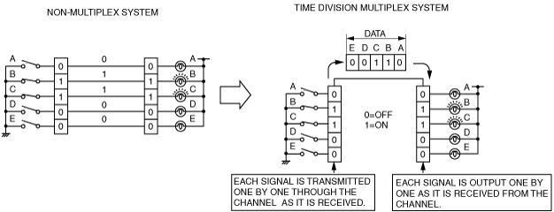
Time Division Multiplex
am2zzn00000584
|
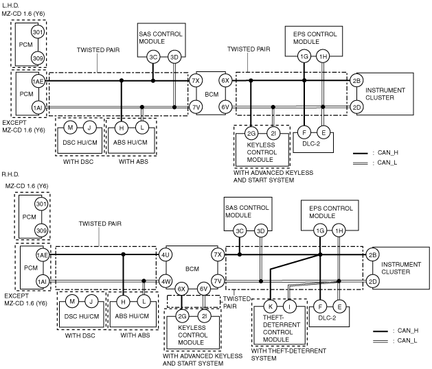
Vehicle CAN System
am2zzn00000594
|
CAN signal table
HS-CAN (ZJ, ZY)
|
Signal |
Multiplex module |
|||||||
|---|---|---|---|---|---|---|---|---|
|
PCM |
ABS HU/CM (with ABS), DSC HU/CM (with DSC) |
BCM |
Keyless control module (with advanced keyless entry and start system) |
SAS control module |
Theft-deterrent control module (with theft-deterrent system) |
EPS control module |
Instrument cluster |
|
|
Immobilizer system related information
|
OUT
|
―
|
―
|
IN
|
―
|
―
|
―
|
IN
|
|
IN
|
―
|
OUT
|
||||||
|
Engine condition
|
OUT
|
IN
|
IN
|
IN
|
IN
|
―
|
IN
|
IN
|
|
Engine torque
|
OUT
|
IN
(DSC)
|
―
|
―
|
―
|
―
|
―
|
―
|
|
Engine speed
|
OUT
|
IN
(DSC)
|
IN
|
IN
|
―
|
IN
|
IN
|
IN
|
|
Vehicle speed
|
OUT
|
―
|
IN
|
IN
|
IN
|
IN
|
―
|
IN
|
|
Accelerator pedal position
|
OUT
|
IN
|
―
|
―
|
―
|
―
|
―
|
―
|
|
Brake pedal switch condition
|
OUT
|
IN
|
IN
|
―
|
―
|
―
|
―
|
―
|
|
Brake system condition
|
OUT
|
IN
|
IN
|
―
|
―
|
―
|
―
|
―
|
|
Distance travelled
|
OUT
|
―
|
―
|
―
|
―
|
―
|
―
|
IN
|
|
Selector lever position
|
OUT
|
―
|
IN
|
―
|
―
|
―
|
―
|
IN
|
|
Gear position
|
OUT
|
IN
(DSC)
|
―
|
―
|
―
|
―
|
―
|
IN
|
|
Target gear position
|
OUT
|
―
|
―
|
―
|
―
|
―
|
―
|
IN
|
|
Tire size
|
OUT
|
IN
|
―
|
―
|
―
|
―
|
―
|
―
|
|
MIL illumination request
|
OUT
|
―
|
―
|
―
|
―
|
―
|
―
|
IN
|
|
Fuel injection amount
|
OUT
|
―
|
―
|
―
|
―
|
―
|
―
|
IN
|
|
Engine coolant temperature
|
OUT
|
―
|
―
|
―
|
―
|
―
|
―
|
IN
|
|
Generator warning light illumination request
|
OUT
|
―
|
―
|
―
|
―
|
―
|
―
|
IN
|
|
Cruise control illumination request
|
OUT
|
―
|
―
|
―
|
―
|
―
|
―
|
IN
|
|
Wheel speed (LF, RF, LR, RR)
|
IN
|
OUT
|
IN
|
―
|
―
|
―
|
―
|
―
|
|
Brake system warning light illumination request
|
―
|
OUT
|
―
|
―
|
―
|
―
|
―
|
IN
|
|
ABS condition
|
IN
|
OUT
|
―
|
―
|
―
|
―
|
―
|
―
|
|
ABS warning light illumination request
|
―
|
OUT
|
―
|
―
|
―
|
―
|
―
|
IN
|
|
Door/liftgate opening and closing
|
―
|
―
|
OUT
|
―
|
―
|
IN
|
―
|
IN
|
|
Door lock-link switch condition
|
―
|
―
|
OUT
|
―
|
―
|
IN
|
―
|
IN
|
|
Key reminder switch condition
|
―
|
―
|
OUT
|
―
|
―
|
―
|
―
|
IN
|
|
Key cylinder switch condition
|
―
|
―
|
OUT
|
―
|
―
|
IN
|
―
|
―
|
|
Turn indicator light illumination request
|
―
|
―
|
OUT
|
―
|
―
|
―
|
―
|
IN
|
|
Liftgate opener condition
|
―
|
―
|
OUT
|
―
|
―
|
IN
|
―
|
―
|
|
High beam illumination request
|
―
|
―
|
OUT
|
―
|
―
|
―
|
―
|
IN
|
|
Front fog light condition
|
―
|
―
|
OUT
|
―
|
―
|
―
|
―
|
IN
|
|
Rear fog light condition
|
―
|
―
|
OUT
|
―
|
―
|
―
|
―
|
IN
|
|
Running light condition
|
IN
|
―
|
OUT
|
―
|
―
|
―
|
―
|
IN
|
|
Parking brake position
|
―
|
―
|
OUT
|
―
|
―
|
―
|
―
|
IN
|
|
Brake fluid level
|
―
|
―
|
OUT
|
―
|
―
|
―
|
―
|
IN
|
|
TNS relay condition
|
IN
|
―
|
OUT
|
―
|
―
|
―
|
―
|
IN
|
|
Oil pressure switch condition
|
―
|
―
|
OUT
|
―
|
―
|
―
|
―
|
IN
|
|
Front wiper switch condition
|
IN
|
―
|
OUT
|
―
|
―
|
―
|
―
|
―
|
|
Running light condition
|
IN
|
―
|
OUT
|
―
|
―
|
―
|
―
|
IN
|
|
Keyless warning buzzer operation request
|
―
|
―
|
―
|
OUT
|
―
|
―
|
―
|
IN
|
|
Keyless indicator light illumination request
|
―
|
―
|
―
|
OUT
|
―
|
―
|
―
|
IN
|
|
Keyless warning light illumination request
|
―
|
―
|
―
|
OUT
|
―
|
―
|
―
|
IN
|
|
Buckle switch condition (driver-side)
|
―
|
―
|
IN
|
―
|
OUT
|
―
|
―
|
IN
|
|
Buckle switch condition (passenger-side)
|
―
|
―
|
―
|
―
|
OUT
|
―
|
―
|
IN
|
|
Air bag system warning buzzer condition
|
―
|
―
|
―
|
―
|
OUT
|
―
|
―
|
IN
|
|
Air bag system warning light illumination request
|
―
|
―
|
―
|
―
|
OUT
|
―
|
―
|
IN
|
|
IN
|
OUT
|
|||||||
|
Steering angle/steering angle sensor condition
|
―
|
IN
(DSC)
|
―
|
―
|
―
|
―
|
OUT
|
―
|
|
EPS condition
|
―
|
―
|
―
|
―
|
―
|
―
|
OUT
|
IN
|
HS-CAN (MZ-CD 1.4 DI Turbo, MZ-CD 1.6 (Y6))
|
Signal |
Multiplex module |
|||||||
|---|---|---|---|---|---|---|---|---|
|
PCM |
ABS HU/CM (with ABS), DSC HU/CM (with DSC) |
BCM |
Keyless control module (with advanced keyless entry and start system) |
SAS control module |
Theft-deterrent control module (with theft-deterrent system) |
EPS control module |
Instrument cluster |
|
|
Immobilizer system related information
|
OUT
|
―
|
―
|
IN
|
―
|
―
|
―
|
IN
|
|
IN
|
―
|
OUT
|
||||||
|
Engine condition
|
OUT
|
IN
|
IN
|
IN
|
IN
|
―
|
IN
|
IN
|
|
Engine torque
|
OUT
|
IN
(DSC)
|
―
|
―
|
―
|
―
|
―
|
―
|
|
Engine speed
|
OUT
|
IN
(DSC)
|
IN
|
IN
|
―
|
IN
|
IN
|
IN
|
|
Vehicle speed
|
OUT
|
―
|
IN
|
IN
|
IN
|
IN
|
―
|
IN
|
|
Accelerator pedal position
|
OUT
|
IN
|
―
|
―
|
―
|
―
|
―
|
―
|
|
IN
|
―
|
―
|
―
|
―
|
―
|
―
|
OUT
|
|
|
Brake pedal switch condition
|
OUT
|
IN
|
IN
|
―
|
―
|
―
|
―
|
―
|
|
IN
|
―
|
―
|
―
|
―
|
―
|
―
|
OUT
|
|
|
Brake system condition
|
OUT
|
IN
|
IN
|
―
|
―
|
―
|
―
|
―
|
|
Distance travelled
|
OUT
|
―
|
―
|
―
|
―
|
―
|
―
|
IN
|
|
Gear position
|
OUT
|
IN
(DSC)
|
―
|
―
|
―
|
―
|
―
|
IN
|
|
Tire size
|
OUT
|
IN
|
―
|
―
|
―
|
―
|
―
|
―
|
|
MIL illumination request
|
OUT
|
―
|
―
|
―
|
―
|
―
|
―
|
IN
|
|
Fuel injection amount
|
OUT
|
―
|
―
|
―
|
―
|
―
|
―
|
IN
|
|
Engine coolant temperature
|
OUT
|
―
|
―
|
―
|
―
|
―
|
―
|
IN
|
|
Generator warning light illumination request
|
OUT
|
―
|
―
|
―
|
―
|
―
|
―
|
IN
|
|
Cruise control illumination request
|
OUT
|
―
|
―
|
―
|
―
|
―
|
―
|
IN
|
|
Wheel speed (LF, RF, LR, RR)
|
IN
|
OUT
|
IN
|
―
|
―
|
―
|
―
|
―
|
|
Brake system warning light illumination request
|
―
|
OUT
|
―
|
―
|
―
|
―
|
―
|
IN
|
|
ABS condition
|
IN
|
OUT
|
―
|
―
|
―
|
―
|
―
|
―
|
|
ABS warning light illumination request
|
―
|
OUT
|
―
|
―
|
―
|
―
|
―
|
IN
|
|
ABS torque data type
|
IN
|
OUT
|
―
|
―
|
―
|
―
|
―
|
―
|
|
Door/liftgate opening and closing
|
―
|
―
|
OUT
|
―
|
―
|
IN
|
―
|
IN
|
|
Door lock-link switch condition
|
―
|
―
|
OUT
|
―
|
―
|
IN
|
―
|
IN
|
|
Key reminder switch condition
|
―
|
―
|
OUT
|
―
|
―
|
―
|
―
|
IN
|
|
Key cylinder switch condition
|
―
|
―
|
OUT
|
―
|
―
|
IN
|
―
|
―
|
|
Turn indicator light illumination request
|
―
|
―
|
OUT
|
―
|
―
|
―
|
―
|
IN
|
|
Liftgate opener condition
|
―
|
―
|
OUT
|
―
|
―
|
IN
|
―
|
―
|
|
High beam illumination request
|
―
|
―
|
OUT
|
―
|
―
|
―
|
―
|
IN
|
|
Front fog light condition
|
―
|
―
|
OUT
|
―
|
―
|
―
|
―
|
IN
|
|
Rear fog light condition
|
―
|
―
|
OUT
|
―
|
―
|
―
|
―
|
IN
|
|
Running light condition
|
IN
|
―
|
OUT
|
―
|
―
|
―
|
―
|
IN
|
|
Parking brake position
|
―
|
―
|
OUT
|
―
|
―
|
―
|
―
|
IN
|
|
Brake fluid level
|
―
|
―
|
OUT
|
―
|
―
|
―
|
―
|
IN
|
|
Oil pressure switch condition
|
―
|
―
|
OUT
|
―
|
―
|
―
|
―
|
IN
|
|
Keyless warning buzzer operation request
|
―
|
―
|
―
|
OUT
|
―
|
―
|
―
|
IN
|
|
Keyless indicator light illumination request
|
―
|
―
|
―
|
OUT
|
―
|
―
|
―
|
IN
|
|
Keyless warning light illumination request
|
―
|
―
|
―
|
OUT
|
―
|
―
|
―
|
IN
|
|
Buckle switch condition (driver-side)
|
―
|
―
|
IN
|
―
|
OUT
|
―
|
―
|
IN
|
|
Buckle switch condition (passenger-side)
|
―
|
―
|
―
|
―
|
OUT
|
―
|
―
|
IN
|
|
Air bag system warning buzzer condition
|
―
|
―
|
―
|
―
|
OUT
|
―
|
―
|
IN
|
|
Air bag system warning light illumination request
|
―
|
―
|
―
|
―
|
OUT
|
―
|
―
|
IN
|
|
IN
|
OUT
|
|||||||
|
Steering angle/steering angle sensor condition
|
―
|
IN
(DSC)
|
―
|
―
|
―
|
―
|
OUT
|
―
|
|
EPS condition
|
―
|
―
|
―
|
―
|
―
|
―
|
OUT
|
IN
|
|
Clutch pedal switch condition
|
IN
|
―
|
―
|
―
|
―
|
―
|
―
|
OUT
|
On-board Diagnostic System Outline
On-board Diagnostic System Construction and Operation
Block Diagram
am2zzn00001140
|
Failure detection function
Fail-safe function
Memory function
Self-malfunction diagnostic function
DTC table
|
DTC |
Malfunction location |
DTC Output Unit |
|---|---|---|
|
U0001:88
|
Module communication error (HS-CAN)
|
• ABS HU/CM (with ABS)
• DSC HU/CM (with DSC)
• BCM
• Keyless control module (with advanced keyless and start system)
• SAS control module
• EPS control module
• Theft-deterrent control module (with theft-deterrent system)
• Instrument cluster
|
|
U0028:87
|
BCM communication error
|
• Keyless control module (with advanced keyless and start system)
|
|
U0073:00
|
Module communication error (CAN bus)
|
• PCM
|
|
U0100:00
|
PCM communication error
|
• ABS HU/CM (with ABS)
• DSC HU/CM (with DSC)
• BCM
• Keyless control module (with advanced keyless and start system)
• EPS control module
• Theft-deterrent control module (with theft-deterrent system)
• Instrument cluster
|
|
U0121:00
|
ABS HU/CM (with ABS) or DSC HU/CM (with DSC) communication error
|
• PCM
• BCM
• EPS control module
• Instrument cluster
|
|
U0126:00
|
EPS control module communication error
|
• DSC HU/CM (with DSC)
|
|
U0131:00
|
EPS control module communication error
|
• Instrument cluster
|
|
U0140:00
|
BCM communication error
|
• PCM
• Theft-deterrent control module (with theft-deterrent system)
• Instrument cluster
|
|
U0151:00
|
SAS control module communication error
|
• PCM
• Instrument cluster
|
|
U0155:00
|
Instrument cluster communication error
|
• PCM
• ABS HU/CM (with ABS)
• DSC HU/CM (with DSC)
• SAS control module
|
|
U0214:00
|
Keyless control module communication error
|
• Instrument cluster
|
|
U2101:00
|
Signal error from instrument cluster
|
• ABS HU/CM (with ABS)
• DSC HU/CM (with DSC)
|
Narrowing down malfunction locations
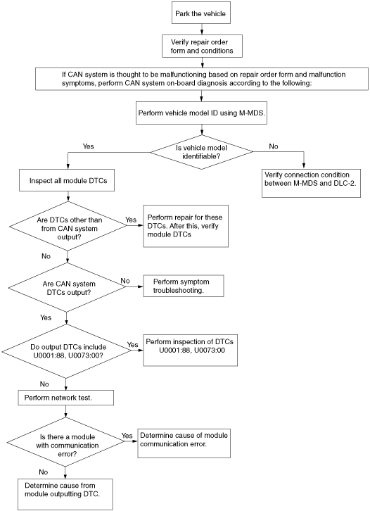
Flowchart
am2zzn00000719
|
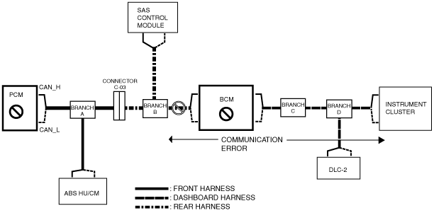
Example (L.H.D.): PCM-related wiring harness open circuit (if DTC is output)
1. Verify the CAN system-related module DTCs using the Mazda Modular Diagnostic System (M-MDS).
|
Module |
Displayed DTC |
Probable malfunction location |
|---|---|---|
|
PCM
|
U0140:00
|
BCM communication error
|
|
U0155:00
|
Instrument cluster communication error
|
am2zzn00001018
|
2. Even though communication among the ABS HU/CM (vehicles with ABS) and SAS control module is normal, a malfunction between the PCM, BCM or BCM and the branch B wiring harness can be considered because communication error DTCs are displayed for the BCM and the instrument cluster.
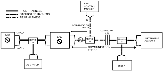
Example (R.H.D.): PCM-related wiring harness open circuit (if DTC is output)
1. Verify the CAN system-related module DTCs using the Mazda Modular Diagnostic System (M-MDS).
|
Module |
Displayed DTC |
Probable malfunction location |
|---|---|---|
|
PCM
|
U0151:00
|
SAS control module communication error
|
|
U0155:00
|
Instrument cluster communication error
|
am2zzn00001019
|
2. Even though communication among the BCM and ABS HU/CM (vehicles with ABS) is normal, a malfunction between the PCM, BCM or BCM and the branch B wiring harness can be considered because communication error DTCs are displayed for the SAS control module and the instrument cluster.