 |
bes3ze00000031
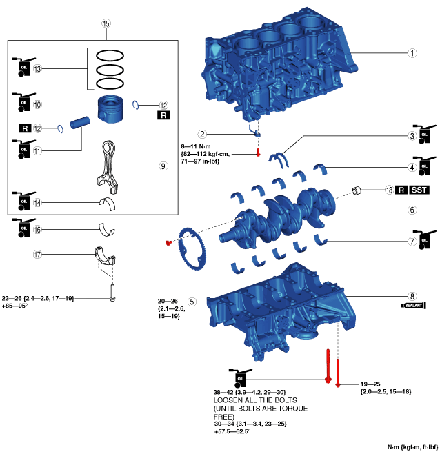
CYLINDER BLOCK ASSEMBLY (I)
id011000504000
1. Assemble in the order indicated in the table.
bes3ze00000031
|
|
1
|
Upper cylinder block
|
|
2
|
Oil jet valve
|
|
3
|
Thrust bearing
|
|
4
|
Upper main bearing
|
|
5
|
Plate
(See Plate Assembly Note.)
|
|
6
|
Crankshaft
|
|
7
|
Lower main bearing
|
|
8
|
Lower cylinder block
|
|
9
|
Connecting rod
|
|
10
|
Piston
|
|
11
|
Piston pin
(See Piston Pin Assembly Note.)
|
|
12
|
Snap ring
(See Snap Ring Assembly Note.)
|
|
13
|
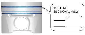
Piston ring
(See Piston Ring Assembly Note.)
|
|
14
|
Upper connecting rod bearing
|
|
15
|
Piston, connecting rod
|
|
16
|
Lower connecting rod bearing
|
|
17
|
Connecting rod cap
|
|
18
|
Pilot bearing (MTX)
(See Pilot Bearing Assembly Note.)
|
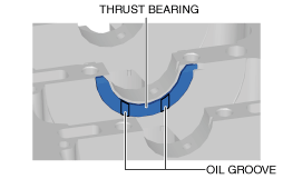
Thrust Bearing And Main Bearing Assembly Note
Thrust bearing
1. Apply clean engine oil to the thrust bearings.
2. Assemble the bearings with the oil groove of the thrust bearing pointed toward the sliding surface.
bes3ze00000032
|
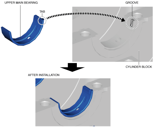
Main bearing
1. Apply clean engine oil to the main bearings.
2. Align the positioning tab of the main bearing with the positioning groove of the lower and upper cylinder block, and assemble the bearings.
bes3ze00000033
|
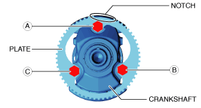
Plate Assembly Note
1. Install the plate using the following procedure:
bes3ze00000034
|
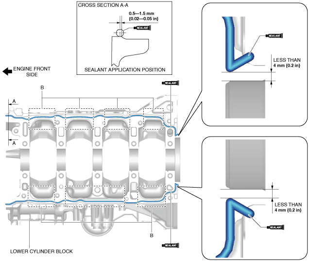
Lower Cylinder Block Assembly Note
1. Completely clean and remove any dirt, sealant or other foreign material that may be adhering to the upper and lower cylinder block.
2. Degrease the contact surfaces of the lower and upper cylinder blocks.
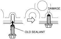
3. When reusing the lower cylinder block installation bolts, clean any old sealant from the bolts.
bpe2ue00000039
|
4. Apply silicon sealant (TB1217D or equivalent) to the lower cylinder block shown in the figure.
bes3ze00000035
|
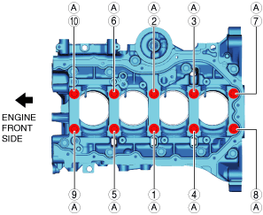
5. Install the lower cylinder block.
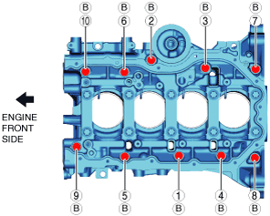
6. Tighten the lower cylinder block installation bolts using the following procedure:
bes3ze00000036
|
bes3ze00000037
|
7. After verifying that silicone sealant protrudes to the rear oil seal press-in part, wipe away the excess silicone sealant.
Piston Pin Assembly Note
1. Remove dirt adhering to the piston pin.
2. Apply engine oil to the piston pin.
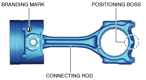
3. Assemble the piston and connecting rod using the following procedure:
bes3ze00000038
|
bes3ze00000039
|
4. Insert the piston pin into the piston and connecting rod.
5. Remove the temporarily assembled connecting rod cap.
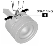
Snap Ring Assembly Note
bes3ze00000040
|
1. Insert a new snap ring using a pair of thin pliers.
bes3ze00000041
|
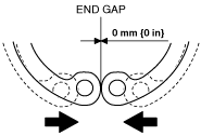
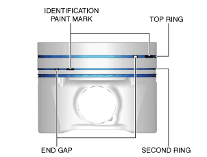
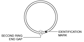
Piston Ring Assembly Note
1. Install the oil ring.
2. Assemble so that the identification paint marks on the top and second rings are visible to the right side of each end gap.
bes3ze00000043
|
bes3ze00000044
|
bes3ze00000045
|
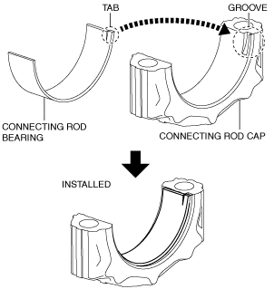
Connecting Rod Bearing Assembly Note
1. Apply engine oil to the connecting rod bearing.
2. Align the positioning tab of the connecting rod bearing with the positioning groove of the connecting rod and connecting rod cap, and assemble the bearings.
bes3ze00000046
|
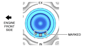
Piston, Connecting Rod Assembly Note
1. Remove the dirt adhering to the piston.
2. Apply engine oil to the sliding part.
3. Insert the piston into the cylinder with the mark on top of the piston facing the intake side.
bes3ze00000047
|
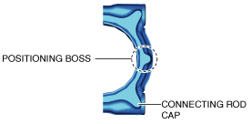
Connecting Rod Cap Assembly Note
adejjw00001214
|
1. Position so that the broken, rough faces of the connecting rods and connecting rod caps are aligned exactly, and assemble the connecting rod caps.
2. Tighten the connecting rod cap bolts in the following two steps.
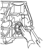
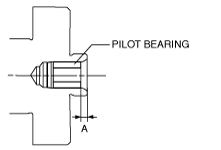
Pilot Bearing Assembly Note
1. Install new pilot bearing to the specified position using the following tools.
bes3ze00000048
|
bes3ze00000049
|