 |
bes3ze00000055
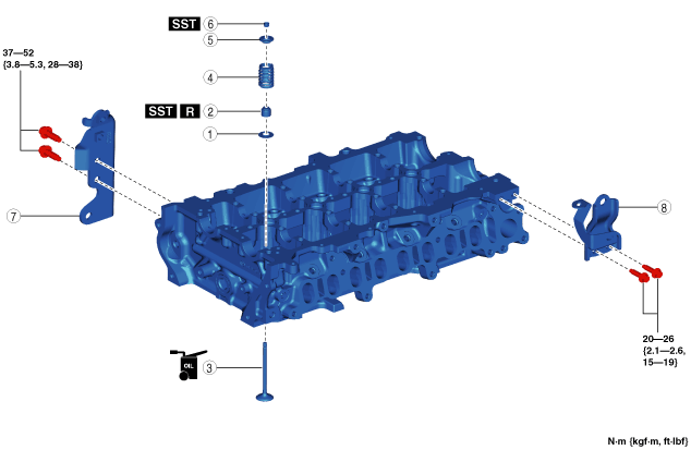
CYLINDER HEAD ASSEMBLY (I)
id011000504300
1. Assemble in the order indicated in the table.
bes3ze00000055
|
|
1
|
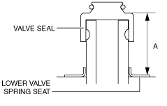
Lower valve spring seat
|
|
2
|
Valve seal
(See Valve Seal Assembly Note.)
|
|
3
|
Valve
|
|
4
|
Valve spring
(See Valve Spring Assembly Note.)
|
|
5
|
Upper valve spring seat
|
|
6
|
Valve keeper
(See Valve Keeper Assembly Note.)
|
|
7
|
Hanger bracket
|
|
8
|
Seal cover bracket
|
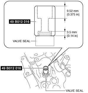
Valve Seal Assembly Note
1. Place the valve seal on the valve guide.
2. Set the SST to the valve seal in the direction shown in the figure.
bes2ze00000055
|
3. Press in the SST by hand and install the valve seal to the valve guide.
bes3ze00000056
|
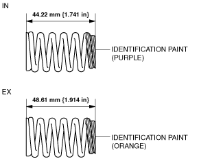
Valve Spring Assembly Note
bes3ze00000057
|
1. Assemble the valve spring with the small diameter side of the valve spring facing upward.
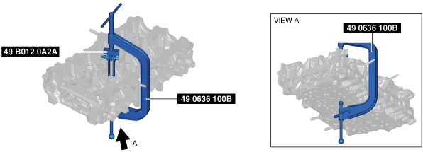
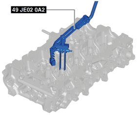
Valve Keeper Assembly Note
1. Install the valve keeper using the SSTs.
When using the SSTs (49 0636 100B, 49 B012 0A2A)
bes3ze00000058
|
When using the SST (49 JE02 0A2) (Europe only)
bes3ze00000059
|