CYLINDER HEAD ASSEMBLY (II)
id011000504400
-
Caution
-
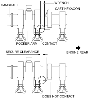
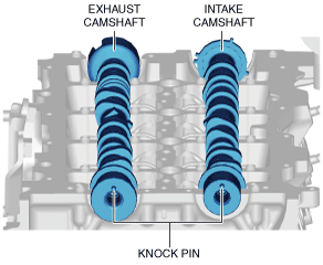
• When rotating the camshaft using a wrench on the cast hexagon, the wrench may contact the rocker arm and damage the rocker arm. To prevent damage to the rocker arm when holding the camshaft on the cast hexagon, use the wrench at engine rear side as shown in the figure to secure a clearance between the cam.
-
Note
-
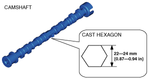
• Width at the cast hexagon of the camshaft is 22—24 mm {0.87—0.94 in}.
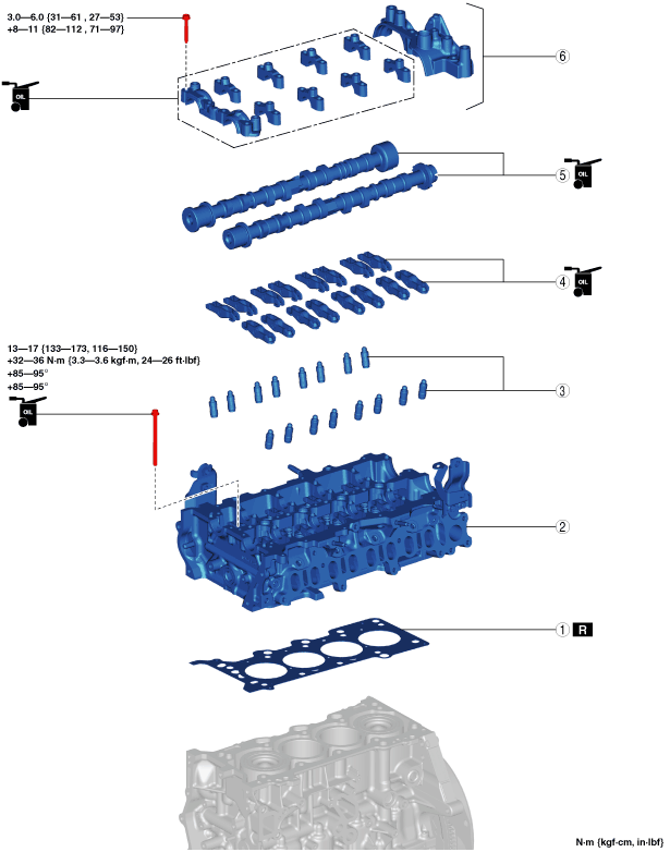
1. Assemble in the order indicated in the table.
|
1
|
Cylinder head gasket
|
|
2
|
Cylinder head
|
|
3
|
HLA
|
|
4
|
Rocker arm
|
|
5
|
Camshaft
|
|
6
|
Camshaft cap
|
Cylinder Head Assembly Note
-
Caution
-
• The end of the glow plug protrudes from the cylinder head (tightened surface of cylinder block). When removing/installing the cylinder head and placing the cylinder head on a workbench, be careful not to allow the end of the glow plug to contact the cylinder block or workbench. Otherwise, the end of the glow plug could be damaged.
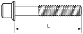
• If the following condition is met, replace the cylinder head bolts.
-
― Length exceeds maximum specification
-
Standard cylinder head bolt length L
-
145.2—145.8 mm {5.717—5.740 in}
-
Maximum cylinder head bolt length L
-
146.5 mm {5.768 in}
1. When a cylinder head bolt is reused, apply engine oil to any part of the following:
-
• Bolt seating surface
• Cylinder head seating surface
2. Tighten the cylinder head bolts in the order shown in the following four steps.
-
Tightening procedure
-
Step 1: 13—17 N·m {133—173 kgf·cm, 116—150 in·lbf}
Step 2: 32—36 N·m {3.3—3.6 kgf·m, 24—26 ft·lbf}
Step 3: 85—95°
Step 4: 85—95°
HLA Assembly Note
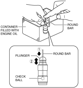
1. Perform HLA air bleeding using the following procedure:
- (1) Put the HLA in a container filled with engine oil.
-
-
Caution
-
• Do not insert the round bar firmly because the check ball spring force is extremely weak.
- (2) While lightly pressing the check ball using a round bar (approx. 1.0 mm {0.039 in} diameter), bleed air by moving the plunger up and down.
-
- (3) Press the end of the plunger in the oil and verify that there is no rebounding feel.
-
-
• If rebounding feel cannot be eliminated, replace the HLA.
2. Install the HLAs to the same positions as before removal.
Rocker Arm Assembly Note
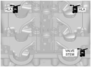
1. Apply engine oil to the HLAs and the end of the valve stems.
2. Install the rocker arms to the same positions as before removal.
Camshaft Assembly Note
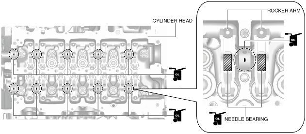
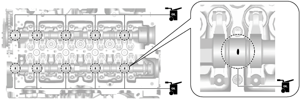
1. Apply SAE 90 gear oil or equivalent, or engine oil to the positions shown in the figure.
2. Apply SAE 90 gear oil or equivalent, or engine oil to the following locations of each camshaft.
-
• Gear sliding surfaces
• Thrust surface of front journal (both surfaces front and back)
-
Note
-
• If oil is applied to the front camshaft cap, oil should not be applied to the thrust surface of the front journal.
3. Set the camshaft on the cylinder heads and align it to the positions shown in the figure.
4. Apply SAE 90 gear oil or equivalent, or engine oil to the central area of each journal on the camshaft.
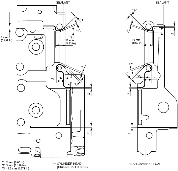
5. Apply sealant (Loctite#962T or equivalent) to the rear side of the cylinder head or rear camshaft cap.
-
Note
-
• To prevent engine oil leakage, seal the journal by applying sealant to the rear side of the cylinder head or rear camshaft cap.
-
Caution
-
• Do not spill sealant on the journal.
• To prevent sealant from hardening, adhere the rear camshaft cap to the cylinder head within 10 min after sealant is applied. Tighten the installation bolts completely soon after adhering.
-
Sealant bead width
-
1—3 mm {0.04—0.11 in}
6. Apply gear oil (SAE 90 or equivalent) or engine oil to the thrust surface of the front camshaft cap.
-
Note
-
• If oil is applied to the front journal thrust surface of each camshaft, oil should not be applied to the front camshaft cap.
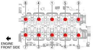
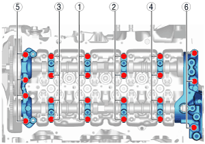
7. Install the camshaft caps in the marked number order, and temporarily tighten the camshaft cap installation bolts in two or three passes evenly.
8. Tighten the camshaft cap installation bolts in two steps in the order shown in the figure.
-
Tightening torque
-
Step 1: 3.0—6.0 N·m {31—61 kgf·cm, 27—53 in·lbf}
Step 2: 8—11 N·m {82—112 kgf·cm, 71—97 in·lbf}