TIMING CHAIN ASSEMBLY
id011000505600
-
Caution
-
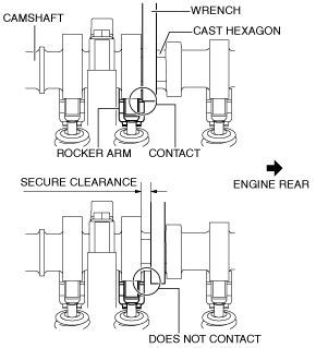
• When rotating the camshaft using a wrench on the cast hexagon, the wrench may contact the rocker arm and damage the rocker arm. To prevent damage to the rocker arm when holding the camshaft on the cast hexagon, use the wrench at engine rear side as shown in the figure to secure a clearance between the cam.
-
Note
-
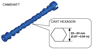
• Width at the cast hexagon of the camshaft is 22—24 mm {0.87—0.94 in}.
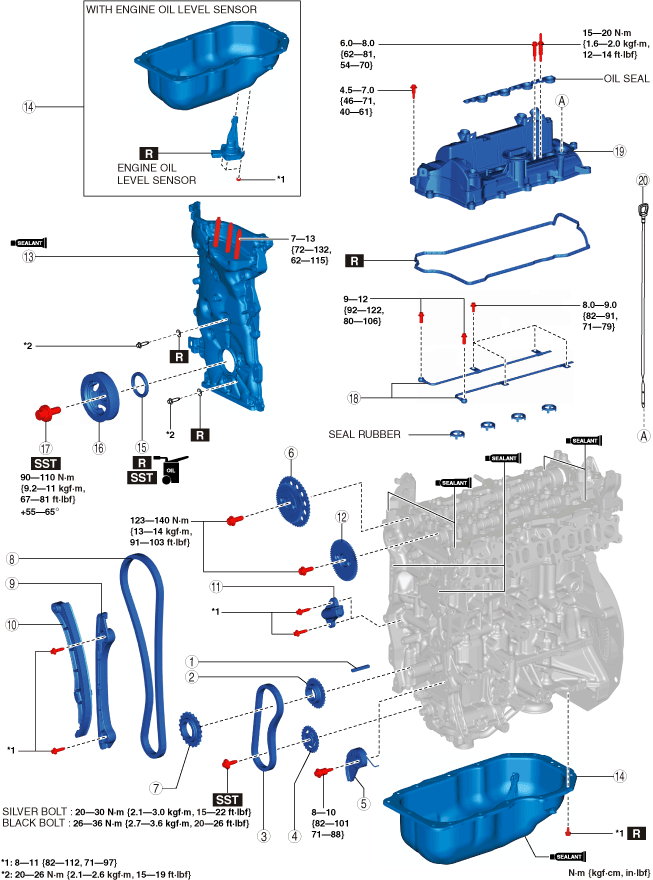
1. Assemble in the order indicated in the table.
|
1
|
Key
|
|
2
|
Oil pump drive sprocket
|
|
3
|
Oil pump chain
|
|
4
|
Oil pump driven sprocket
|
|
5
|
Oil pump chain tensioner
|
|
6
|
Exhaust Camshaft Sprocket
|
|
7
|
Crankshaft sprocket
|
|
8
|
Timing chain
|
|
9
|
Timing chain guide
|
|
10
|
Timing chain tensioner arm
|
|
11
|
Timing chain tensioner
|
|
12
|
Intake Camshaft Sprocket
|
|
13
|
Engine front cover
|
|
14
|
Oil pan component
|
|
15
|
Front oil seal
|
|
16
|
Crankshaft pulley
|
|
17
|
Crankshaft pulley lock bolt
|
|
18
|
Oil shower pipe
|
|
19
|
Cylinder head cover
|
|
20
|
Dipstick
|
Oil Pump Driven Sprocket Assembly Note
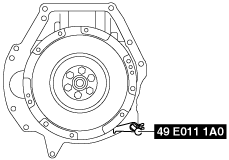
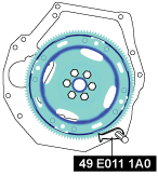
1. Hold the crankshaft using the SST.
MTX
ATX
2. Tighten the oil pump driven sprocket installation bolt.
-
Tightening torque
-
Silver bolt: 20—30 N·m {2.1—3.0 kgf·m, 15—22 ft·lbf}
Black bolt: 26—36 N·m {2.7—3.6 kgf·m, 20—26 ft·lbf}
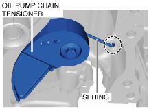
Oil Pump Chain Tensioner Assembly Note
1. Temporarily assemble the oil pump chain tensioner.
2. Verify that the spring of the oil pump chain tensioner is in the hole of the lower cylinder block.
-
• If the spring is not in the hole, perform the temporary assembly of the oil pump chain tensioner again.
3. Tighten the oil pump chain tensioner installation bolt.
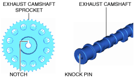
Exhaust Camshaft Sprocket Assembly Note
1. Align the knock pin on the end of the exhaust camshaft with the notch on the exhaust camshaft sprocket side, and temporarily assemble the bolt.
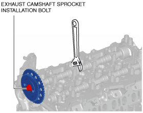
2. Hold the exhaust camshaft using a wrench on the cast hexagon, and tighten the exhaust camshaft sprocket installation bolt.
-
Tightening torque
-
123—140 N·m {13—14 kgf·m, 91—103 ft·lbf}
Timing Chain Assembly Note
-
Caution
-
• If the camshaft or crankshaft is rotated before assembling the timing chain, the valve may contact the piston and the engine could be damaged.
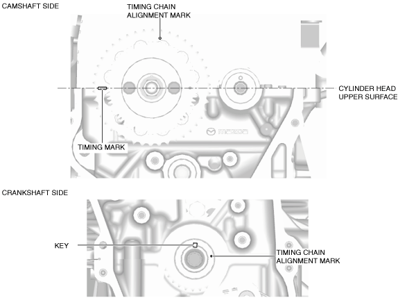
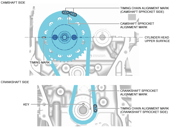
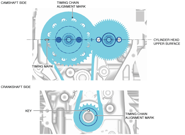
1. Verify that the timing marks and the key are aligned to the position shown in the figure.
-
• If the key and the timing mark are not in the position shown in the figure, adjust their positions to set cylinder No.1 to top dead center (TDC) using the following procedure:
-
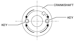
1. Rotate the crankshaft either left or right so that the key is in the complete horizontal position.
-
Caution
-
• Be careful not to rotate the crankshaft to an angle greater than 90 degrees.
2. Rotate the exhaust camshaft to adjust the timing mark position.
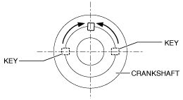
3. Rotate the crankshaft as shown in the figure to adjust the key position.
-
Caution
-
• Be careful not to rotate the crankshaft to an angle greater than 90 degrees.
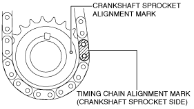
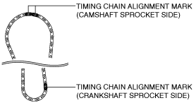
2. Align the timing chain alignment mark (crankshaft sprocket side) with the crankshaft sprocket alignment mark.
-
Note
-
• There are two timing chain alignment marks as shown in the figure.
3. Install the timing chain and crankshaft sprocket as a single unit while aligning the marks on each sprocket and the timing chain as shown in the figure.
4. Install the timing chain guide.
5. Install the timing chain tensioner arm.
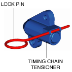
6. Install the timing chain tensioner.
7. After installing the timing chain tensioner, remove the installed rod, and then apply tension to the timing chain.
-
• If a new timing chain tensioner is used, remove the installed lock pin.
8. Verify that there is no looseness in the timing chain, and re-verify that each sprocket is in the specified location.
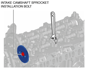
Intake Camshaft Sprocket Assembly Note
-
Caution
-
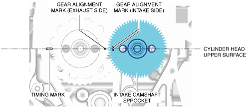
• Align the gear alignment marks and assemble the sprocket.
1. Align the knock pin on the end of the intake camshaft with the knock pin installation hole on the intake camshaft sprocket side, and temporarily assemble the bolt.
-
Note
-
• Finely adjust the knock pin position by rotating the camshaft and align the knock pin with the installation hole.
2. Hold the intake camshaft using a wrench on the cast hexagon, and tighten the intake camshaft sprocket installation bolt.
3. Rotate the crankshaft clockwise two turns and inspect the valve timing.
Engine Front Cover Assembly Note
-
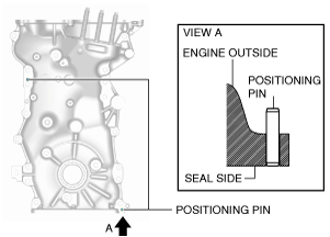
Note
-
• For a new engine front cover, the positioning pins in the two locations shown in the figure project to the outside of the engine.
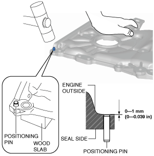
1. If the engine front cover is newly replaced, tap the positioning pins in the two locations to the seal surface side.
-
Caution
-
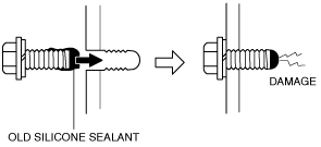
• If a bolt with sealant adhering to it is used, it could result in cracks in the cylinder head and cylinder block.
2. When reusing an engine front cover installation bolts, remove sealant adhering to the bolts.
-
Caution
-
• If oil, dirt and sealant remains on the sealant application area, the silicone sealant will not seal which will cause oil leakage.
3. Completely clean and remove any oil, dirt, sealant or other foreign matter that may be adhering to the engine front cover, cylinder head, and cylinder block.
-
Caution
-
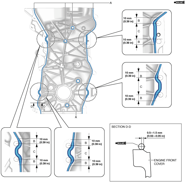
• Apply the silicon sealant in a single, unbroken line.
• To prevent silicone sealant from hardening, adhere the engine front cover and the cylinder block firmly within 10 min. after applying silicone sealant. After adhering them, tighten the installation bolts immediately.
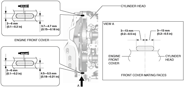
4. Apply silicone sealant (TB1217D or equivalent) to the engine front cover as shown in the figure.
-
Bead thickness
-
A: 2—6 mm {0.1—0.2 in}
B: 4—6 mm {0.16—0.23 in}
C: 4—8 mm {0.2—0.3 in}
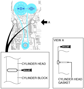
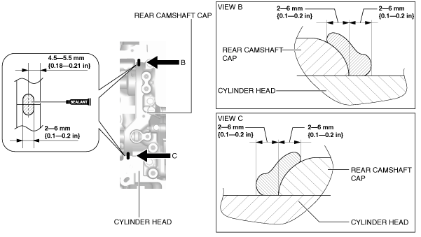
5. Apply silicone sealant to the areas shown in the figure.
-
Caution
-
• Apply the silicone sealant so that it goes into the cylinder head gasket.
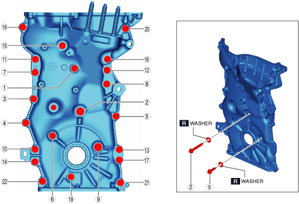
6. Install the engine front cover to the engine.
-
Caution
-
• For the number 2 and 9 bolts of the tightening order, install the bolts with new washers.
7. Tighten the engine front cover installation bolts in the order shown in the figure.
-
Tightening torque
-
20—26 N·m {2.1—2.6 kgf·m, 15—19 ft·lbf}
-
Note
-
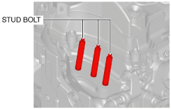
• Install stud bolts because there are no stud bolts installed on a new engine front cover.
• If the engine front cover is reused, tighten the stud bolts because they may have loosened.
8. Tighten the engine front cover stud bolts.
-
Tightening torque
-
7—13 N·m {72—132 kgf·cm, 62—115 in·lbf}
Oil Pan Component Assembly Note
-
Caution
-
• If the engine oil level sensor is removed, it is necessary to replace it with a new one. (with engine oil level sensor)
1. Completely clean and remove any oil, dirt, sealant or other foreign material that may be adhering to the cylinder block and oil pan.
-
Caution
-
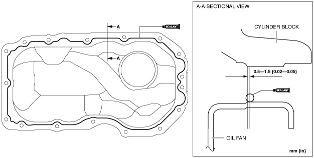
• Apply the silicon sealant in a single, unbroken line around the whole perimeter.
• To prevent silicone sealant from hardening, adhere the oil pan to the cylinder block within 10 min. after silicone sealant is applied. Tighten the installation bolts completely soon after adhering.
2. Apply silicone sealant (TB1217D or equivalent) to the oil pan and the cylinder block.
-
Thickness
-
3.0—7.0 mm {0.12—0.27 in}
3. Install the oil pan to the cylinder block.
-
Caution
-
• Use new bolts because the oil pan installation bolts cannot be reused.
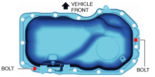
4. Install the oil pan using the following procedure:
- (1) Temporarily tighten the two bolts shown in the figure.
-
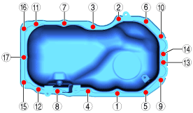
- (2) Tighten the bolts in the order shown in the figure.
-
-
Tightening torque
-
8—11 N·m {82—112 kgf·cm, 71—97 in·lbf}
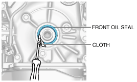
Front Oil Seal Assembly Note
1. Apply clean engine oil to the inner surface of a new front oil seal.
2. Insert the front oil seal into the engine front cover by hand.
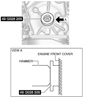
3. Tap the oil seal in evenly using the SST and a hammer.
-
Front oil seal press-in amount
-
0—0.5 mm {0—0.019 in} from engine front cover
Crankshaft Pulley Lock Bolt Assembly Note
1. Hold the crankshaft using the SST.
MTX
ATX
2. Tighten the crankshaft pulley lock bolt in the order shown in the following two steps.
-
Tightening torque
-
Step 1: 90—110 N·m {9.2—11 kgf·m, 67—81 ft·lbf}
Step 2: 55—65°
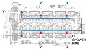
Oil Shower Pipe Assembly Note
1. Install the oil shower pipe in the order shown in the figure.
Tightening torque
|
Installation position
|
Tightening torque
|
|
1
|
9—12 N·m {92—122 kgf·cm, 80—106 in·lbf}
|
|
2, 3
|
8.0—9.0 N·m {82—91 kgf·cm, 71—79 in·lbf}
|
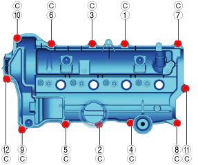
Cylinder Head Cover Assembly Note
-
Caution
-
• To assure the sealing performance of the cylinder head cover, be careful of the following:
-
― Verify that the cylinder head cover gasket is inserted into the cylinder head cover groove and install the cylinder head cover.
― Completely clean and remove any oil, dirt, sealant or other foreign material from the seal surface.
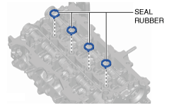
1. Install the seal rubber on the cylinder head.
-
• Verify if the seal rubber has been damaged and if so replace it.
-
― The seal rubber can be reused even though the cylinder head cover causes contact marks on the seal rubber. However, if there is damage such as cracks and chips which may cause the seal rubber to tear, replace it.
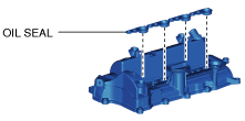
2. Install the oil seal on the cylinder head cover.
-
• Verify if the oil seal shown in the figure has been damaged and if so replace it.
3. Insert a new cylinder head cover gasket into the cylinder head cover groove.
-
Caution
-
• To prevent silicone sealant from hardening, adhere the cylinder head cover and the cylinder head firmly within 10 min. after applying silicone sealant. After adhering them, tighten the installation bolts immediately.
4. Apply silicone sealant (TB1217D or equivalent) to the areas shown in the figure.
-
Engine front side
-
-
Engine rear side
-
5. Install the cylinder head cover.
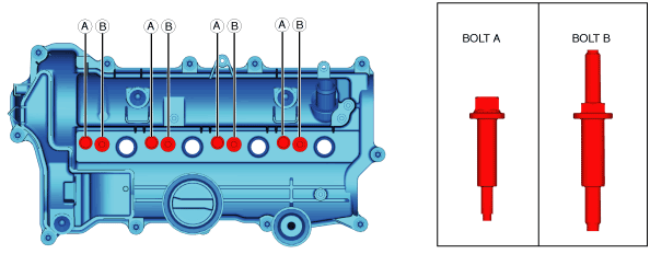
6. Tighten the cylinder head cover installation bolts using the following procedure:
- (1) Tighten the cylinder head cover installation bolts A and B.
-
-
Tightening torque
-
Bolt A: 6.0—8.0 N·m {62—81 kgf·cm, 54—70 in·lbf}
Bolt B: 15—20 N·m {1.6—2.0 kgf·m, 12—14 ft·lbf}
-
Note
-
• The tightening order for installation bolts A and B is optional.
- (2) Tighten cylinder head cover installation bolts C in the order shown in the figure.
-
-
Tightening torque
-
4.5—7.0 N·m {46—71 kgf·cm, 40—61 in·lbf}