 |
am2zzw00011080
ENGINE REMOVAL/INSTALLATION [SKYACTIV-G 1.3, SKYACTIV-G 1.5]
id0110q3800400
1. Disconnect the negative battery cable. (See NEGATIVE BATTERY CABLE DISCONNECTION/CONNECTION.)
2. Remove the plug hole plate. (See PLUG HOLE PLATE REMOVAL/INSTALLATION [SKYACTIV-G 1.3, SKYACTIV-G 1.5].)
3. Remove the air cleaner, air hose and fresh air duct as a single unit. (See INTAKE-AIR SYSTEM REMOVAL/INSTALLATION [SKYACTIV-G 1.3, SKYACTIV-G 1.5].)
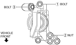
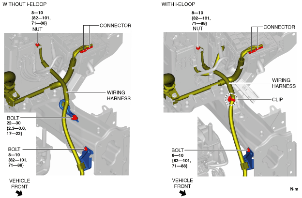
4. Remove the bolts, nut and connector shown in the figure, and set the wiring harness aside.
am2zzw00011080
|
5. Remove the battery tray and PCM component. (See BATTERY REMOVAL/INSTALLATION [SKYACTIV-G 1.3, SKYACTIV-G 1.5].)
6. Remove the front under cover No.1 and No.2. (See FRONT UNDER COVER No.1 REMOVAL/INSTALLATION.) (See FRONT UNDER COVER No.2 REMOVAL/INSTALLATION.)
7. Remove the front splash shield. (See SPLASH SHIELD REMOVAL/INSTALLATION.)
8. Drain the engine coolant. (See ENGINE COOLANT REPLACEMENT [SKYACTIV-G 1.3, SKYACTIV-G 1.5].)
9. Drain the transaxle oil (MTX) or ATF (ATX). (See MANUAL TRANSAXLE OIL REPLACEMENT [F65M-R].) (See MANUAL TRANSAXLE OIL REPLACEMENT [F66M-R].) (See AUTOMATIC TRANSAXLE FLUID (ATF) REPLACEMENT [CW6A-EL].)
10. Remove the front wheels and tires. (See GENERAL PROCEDURES (BRAKE).)
11. Disconnect the selector cable. (ATX) (See AUTOMATIC TRANSAXLE SHIFT MECHANISM REMOVAL/INSTALLATION.)
12. Disconnect the control cable. (MTX) (See MANUAL TRANSAXLE SHIFT MECHANISM REMOVAL/INSTALLATION [F65M-R].)(See MANUAL TRANSAXLE SHIFT MECHANISM REMOVAL/INSTALLATION [F66M-R].)
13. Remove the clutch release cylinder with the pipe still connected. (MTX) (See CLUTCH RELEASE CYLINDER REMOVAL/INSTALLATION [F65M-R].)(See CLUTCH RELEASE CYLINDER REMOVAL/INSTALLATION [F66M-R].)
14. Disconnect the vacuum hose. (See VACUUM HOSE REMOVAL/INSTALLATION [L.H.D.].)(See VACUUM HOSE REMOVAL/INSTALLATION [R.H.D.].)
15. Disconnect evaporative hose No.1 from the engine side. (See PURGE SOLENOID VALVE REMOVAL/INSTALLATION [SKYACTIV-G 1.3, SKYACTIV-G 1.5].)
16. Disconnect the fuel hose from the engine side. (See QUICK RELEASE CONNECTOR REMOVAL/INSTALLATION [SKYACTIV-G 1.3, SKYACTIV-G 1.5].)
17. Disconnect the upper radiator hose. (See COOLING FAN MOTOR REMOVAL/INSTALLATION [SKYACTIV-G 1.3, SKYACTIV-G 1.5].)
18. Disconnect the heater hose. (See A/C UNIT REMOVAL/INSTALLATION.)
19. Disconnect the lower radiator hose. (See RADIATOR REMOVAL/INSTALLATION [SKYACTIV-G 1.3, SKYACTIV-G 1.5].)
20. Remove the generator drive belt. (See DRIVE BELT REMOVAL/INSTALLATION [SKYACTIV-G 1.3, SKYACTIV-G 1.5].)
21. Remove the A/C compressor with the cooler hose still connected and secure it using wire or rope so that it is out of the way. (with A/C) (See A/C COMPRESSOR REMOVAL/INSTALLATION [SKYACTIV-G 1.3, SKYACTIV-G 1.5].)
22. Remove the TWC installation nuts (exhaust manifold side) and secure the TWC using wire or rope so that it is out of the way. (See EXHAUST SYSTEM REMOVAL/INSTALLATION [SKYACTIV-G 1.3, SKYACTIV-G 1.5].)
23. Disconnect the front drive shaft from the transaxle side and set the drive shaft out of the way. (See FRONT DRIVE SHAFT REMOVAL/INSTALLATION.)
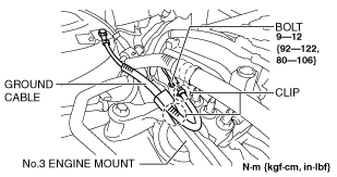
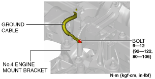
24. Remove the bolt and clips, and set the ground cable aside.
RH
am2zzw00011081
|
LH
am2zzw00011082
|
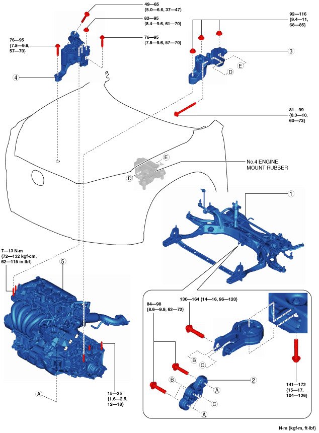
25. Remove in the order indicated in the table.
26. Install in the reverse order of removal.
27. Refill the transaxle oil (MTX) or ATF (ATX). (See MANUAL TRANSAXLE OIL REPLACEMENT [F65M-R].) (See MANUAL TRANSAXLE OIL REPLACEMENT [F66M-R].) (See AUTOMATIC TRANSAXLE FLUID (ATF) REPLACEMENT [CW6A-EL].)
28. Refill the engine coolant. (See ENGINE COOLANT REPLACEMENT [SKYACTIV-G 1.3, SKYACTIV-G 1.5].)
29. Start the engine, and inspect and adjust the following:
am2zzw00011083
|
|
1
|
No.1 engine mount rubber, front crossmember component
|
|
2
|
No.1 engine mount bracket
|
|
3
|
No.4 engine mount bracket
|
|
4
|
No.3 engine mount
|
|
5
|
Engine, transaxle
|
No.1 Engine Mount Rubber, Front Crossmember Component Removal Note
1. Disconnect the service plug. (with i-ELOOP) (See SERVICE PLUG DISCONNECTION/CONNECTION [i-ELOOP].)
2. Disconnect the generator terminal B cable. (with i-ELOOP) (See GENERATOR REMOVAL/INSTALLATION [WITH i-ELOOP (SKYACTIV-G 1.3, SKYACTIV-G 1.5)].)
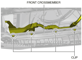
3. Remove the clips shown in the figure and set the wiring harness aside. (with i-ELOOP)
am2zzw00011084
|
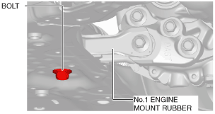
4. Loosen the No.1 engine mount rubber installation bolt. (front crossmember side)
am2zzw00011085
|
5. Remove the No.1 engine mount rubber and the front crossmember component as a single unit. (See FRONT CROSSMEMBER REMOVAL/INSTALLATION [SKYACTIV-G 1.3, SKYACTIV-G 1.5].)
No.3 Engine Mount, No.4 Engine Mount Bracket Removal Note
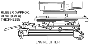
1. Secure the engine and transaxle using a commercially available engine lifter.
am2zzw00011086
|
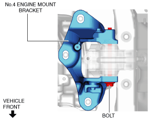
2. Remove the No.4 engine mount bracket.
3. Remove the No.3 engine mount.
Engine Mount Installation Note
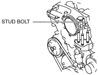
1. Tighten the engine front cover stud bolts.
am3uuw00008803
|
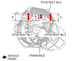
2. Measure the projection of the transaxle stud bolts.
am2zzw00011087
|
3. Secure the engine and transaxle using a commercially available engine lifter.
am2zzw00011086
|
4. Temporarily tighten the No.3 engine mount installation bolts and nuts using the following procedure:
SKYACTIV-G 1.3, SKYACTIV-G 1.5 (with 4-1 exhaust system)
am2zzw00011088
|
SKYACTIV-G 1.5 (with 4-2-1 exhaust system)
ac5uuw00003037
|
SKYACTIV-G 1.3, SKYACTIV-G 1.5 (with 4-1 exhaust system)
am2zzw00011089
|
SKYACTIV-G 1.5 (with 4-2-1 exhaust system)
ac5uuw00003038
|
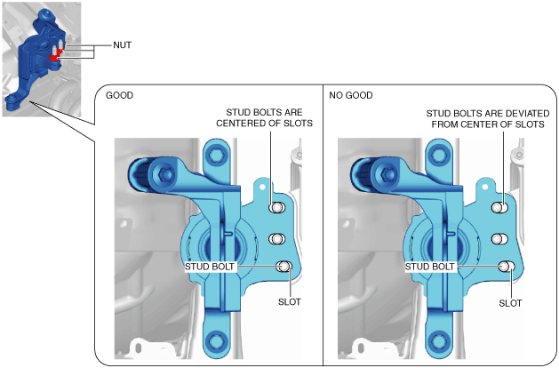
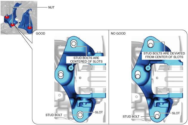
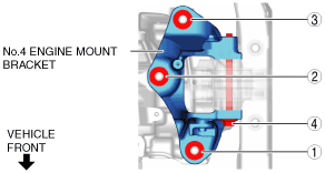
5. Temporarily tighten the No.4 engine mount bracket installation bolt and nuts using the following procedure:
am2zzw00011090
|
am2zzw00011091
|
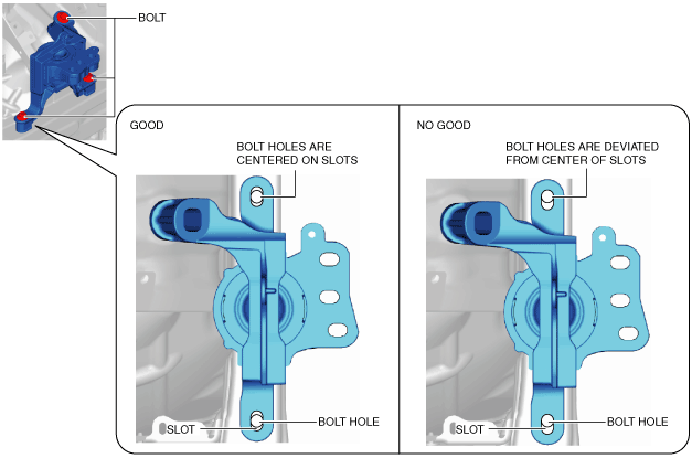
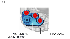
6. Install the No.1 engine mount bracket and temporarily tighten the bolts shown in the figure.
am2zzw00011092
|
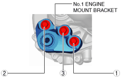
7. Tighten the No.1 engine mount bracket installation bolts in the order shown in the figure.
am2zzw00011093
|
8. Install the No.1 engine mount rubber and the front crossmember component as a single unit. (See FRONT CROSSMEMBER REMOVAL/INSTALLATION [SKYACTIV-G 1.3, SKYACTIV-G 1.5].)
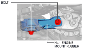
9. Temporarily tighten the No.1 engine mount rubber installation bolts.
am2zzw00011094
|
10. Tighten the No.3 engine mount installation bolts and nuts in the order shown in the figure.
SKYACTIV-G 1.3, SKYACTIV-G 1.5 (with 4-1 exhaust system)
am2zzw00011095
|
SKYACTIV-G 1.5 (with 4-2-1 exhaust system)
am3zzw00014968
|
Tightening torque
|
Installation position |
Tightening torque |
|---|---|
|
1
|
76—95 N·m {7.8—9.6 kgf·m, 57—70 ft·lbf}
|
|
2
|
82—95 N·m {8.4—9.6 kgf·m, 61—70 ft·lbf}
|
|
3
|
49—65 N·m {5.0—6.6 kgf·m, 37—47 ft·lbf}
|
11. Tighten the No.4 engine mount bracket installation bolt and nuts in the order shown in the figure.
am2zzw00011096
|
Tightening torque
|
Installation position |
Tightening torque |
|---|---|
|
1, 2, 3
|
92—116 N·m {9.4—11 kgf·m, 68—85 ft·lbf}
|
|
4
|
81—99 N·m {8.3—10 kgf·m, 60—73 ft·lbf}
|
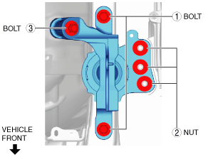
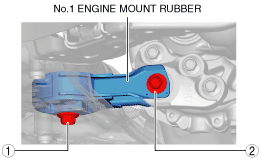
12. Tighten the No.1 engine mount rubber installation bolts in the order shown in the figure.
am2zzw00011097
|
Tightening torque
|
Installation position |
Tightening torque |
|---|---|
|
1
|
141—172 N·m {15—17 kgf·m, 104—126 ft·lbf}
|
|
2
|
130—164 N·m {14—16 kgf·m, 96—120 ft·lbf}
|
13. Install the clips shown in the figure. (with i-ELOOP)
am2zzw00011084
|
14. Connect the generator terminal B cable. (with i-ELOOP) (See GENERATOR REMOVAL/INSTALLATION [WITH i-ELOOP (SKYACTIV-G 1.3, SKYACTIV-G 1.5)].)
15. Install the service plug. (with i-ELOOP) (See SERVICE PLUG DISCONNECTION/CONNECTION [i-ELOOP].)