 |
am2zzw00011098
ENGINE DISASSEMBLY/ASSEMBLY [SKYACTIV-G 1.3, SKYACTIV-G 1.5]
id0110q3800500
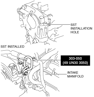
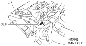
1. To enable to install the SST, disconnect the clip shown in the figure and set the wiring harness aside.
am2zzw00011098
|
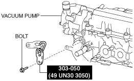
2. Install the SST and the following bolt to the position shown in the figure.
Engine front side
am6zzw00011712
|
Engine rear side
am6zzw00011713
|
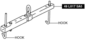
3. Engage the hooks of the SST (49 L017 5A0) to the SST (49 UN30 3050).
am6zzw00011714
|
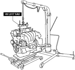
4. To ensure the safety of the work (control engine and transaxle sway), set a hoist as shown in the figure.
am6zzw00011715
|
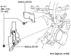
5. Remove the insulator shown in the figure. (SKYACTIV-G 1.5 (with 4-2-1 exhaust system))
am6zzw00011716
|
6. Remove the exhaust system. (See EXHAUST SYSTEM REMOVAL/INSTALLATION [SKYACTIV-G 1.3, SKYACTIV-G 1.5].)
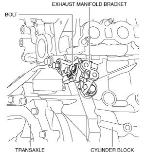
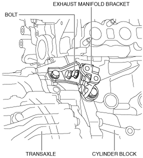
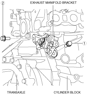
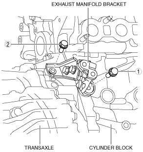
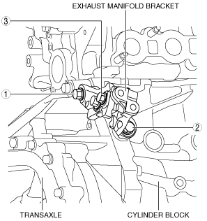
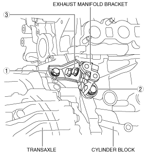
7. Remove the exhaust manifold bracket using the following procedure: (SKYACTIV-G 1.5 (with 4-2-1 exhaust system))
MTX
am3zzw00014970
|
ATX
am3zzw00014971
|
MTX
am3zzw00014972
|
ATX
am3zzw00014973
|
MTX
am3zzw00014974
|
ATX
am3zzw00014975
|
8. Remove the bracket No.1 (drive shaft bracket). (See FRONT DRIVE SHAFT REMOVAL/INSTALLATION.)
9. Remove the starter. (See STARTER REMOVAL/INSTALLATION [SKYACTIV-G 1.3, SKYACTIV-G 1.5].)
10. Fix the drive plate using the crankshaft pulley lock bolt. (ATX)
11. Remove the torque converter installation nut from the starter installation hole. (See AUTOMATIC TRANSAXLE REMOVAL/INSTALLATION [CW6A-EL].)
12. Disconnect the engine and transaxle, and lower only the engine from the engine lifter. (See MANUAL TRANSAXLE REMOVAL/INSTALLATION [F65M-R](MTX).) (See MANUAL TRANSAXLE REMOVAL/INSTALLATION [F66M-R (SKYACTIV-G 1.5)](MTX).) (See AUTOMATIC TRANSAXLE REMOVAL/INSTALLATION [CW6A-EL] (ATX).)
13. Remove the generator. (See GENERATOR REMOVAL/INSTALLATION [WITHOUT i-ELOOP (SKYACTIV-G 1.3, SKYACTIV-G 1.5)].) (See GENERATOR REMOVAL/INSTALLATION [WITH i-ELOOP (SKYACTIV-G 1.3, SKYACTIV-G 1.5)].)
14. Remove the intake-air system. (See INTAKE-AIR SYSTEM REMOVAL/INSTALLATION [SKYACTIV-G 1.3, SKYACTIV-G 1.5].)
15. Remove the fuel injectors. (See FUEL INJECTOR REMOVAL/INSTALLATION [SKYACTIV-G 1.3, SKYACTIV-G 1.5].)
16. Remove the camshaft position (CMP) sensor. (See CAMSHAFT POSITION (CMP) SENSOR REMOVAL/INSTALLATION [SKYACTIV-G 1.3, SKYACTIV-G 1.5].)
17. Remove the vacuum pump. (See VACUUM PUMP REMOVAL/INSTALLATION [SKYACTIV-G 1.3, SKYACTIV-G 1.5].)
18. Remove the high pressure fuel pump and rear housing. (See HIGH PRESSURE FUEL PUMP REMOVAL/INSTALLATION [SKYACTIV-G 1.3, SKYACTIV-G 1.5].)
19. Remove the oil filter. (See OIL FILTER REPLACEMENT [SKYACTIV-G 1.3, SKYACTIV-G 1.5].)
20. Remove the oil pressure switch. (SKYACTIV-G 1.3, SKYACTIV-G 1.5 (with 4-1 exhaust system)) (See OIL PRESSURE INSPECTION [SKYACTIV-G 1.3, SKYACTIV-G 1.5].)
21. Remove the engine oil solenoid valve. (SKYACTIV-G 1.5 (with 4-2-1 exhaust system)) (See ENGINE OIL SOLENOID VALVE REMOVAL/INSTALLATION [SKYACTIV-G 1.3, SKYACTIV-G 1.5].)
22. Remove the crankshaft position (CKP) sensor. (See CRANKSHAFT POSITION (CKP) SENSOR REMOVAL/INSTALLATION [SKYACTIV-G 1.3, SKYACTIV-G 1.5].)
23. Remove the ignition coils. (SKYACTIV-G 1.3, SKYACTIV-G 1.5 (with 4-1 exhaust system)) (See IGNITION COIL/ION SENSOR REMOVAL/INSTALLATION [SKYACTIV-G 1.3, SKYACTIV-G 1.5].)
24. Remove the ignition coil/ion sensors. (SKYACTIV-G 1.5 (with 4-2-1 exhaust system)) (See IGNITION COIL/ION SENSOR REMOVAL/INSTALLATION [SKYACTIV-G 1.3, SKYACTIV-G 1.5].)
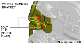
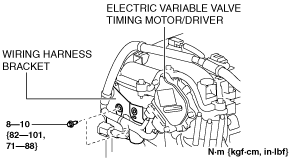
25. Remove the wiring harness bracket shown in the figure.
SKYACTIV-G 1.3, SKYACTIV-G 1.5 (with 4-1 exhaust system)
am2zzw00011099
|
SKYACTIV-G 1.5 (with 4-2-1 exhaust system)
am3zzw00014684
|
26. Remove the emission harness.
27. Remove the water pump drive belt. (See DRIVE BELT REMOVAL/INSTALLATION [SKYACTIV-G 1.3, SKYACTIV-G 1.5].)
28. Remove the clutch cover and clutch disc. (MTX) (See CLUTCH UNIT REMOVAL/INSTALLATION [F65M-R].) (SeeCLUTCH UNIT REMOVAL/INSTALLATION [F66M-R].)
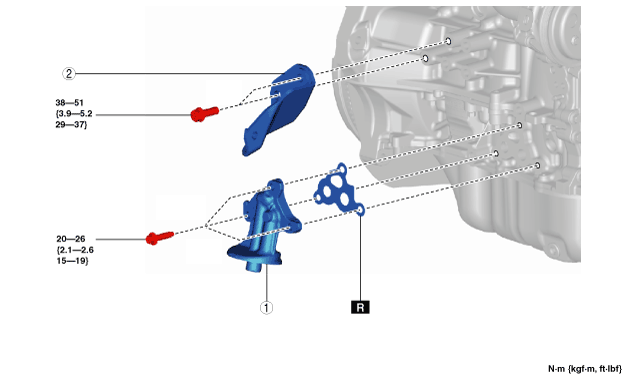
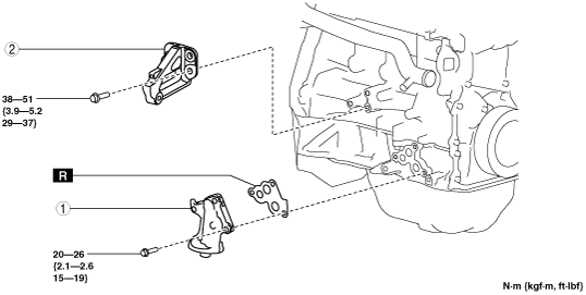
29. Remove in the order indicated in the table
30. Assemble in the reverse order of disassembly.
SKYACTIV-G 1.3, SKYACTIV-G 1.5 (with 4-1 exhaust system)
am2zzw00011100
|
|
1
|
Oil filter body
|
|
2
|
Exhaust manifold bracket
|
SKYACTIV-G 1.5 (with 4-2-1 exhaust system)
am2zzw00011101
|
|
1
|
Oil filter body
|
|
2
|
Exhaust manifold bracket
|
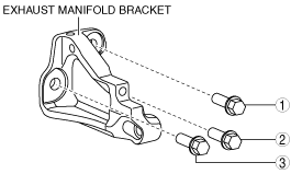
Exhaust Manifold Bracket Installation Note (SKYACTIV-G 1.5 (With 4-2-1 Exhaust System))
1. Temporarily tighten the exhaust manifold bracket installation bolts.
2. Tighten the bolt in the order shown in the figure.
am3zzw00014685
|
Oil Filter Body Installation Note
1. After tightening the three bolts, tighten the first tightened bolt to the specified tightening torque again.