 |
am2zzw00011509
PARKING SENSOR CONTROL MODULE INSPECTION
id092200023600
1. Disconnect the negative battery cable. (See NEGATIVE BATTERY CABLE DISCONNECTION/CONNECTION.)
2. Remove the following parts:
3. Connect the negative battery cable. (See NEGATIVE BATTERY CABLE DISCONNECTION/CONNECTION.)
4. Verify that the voltages of each of the terminals are as indicated in the terminal voltage table (reference).
Terminal Voltage Table (Reference)
am2zzw00011509
|
|
Terminal |
Signal name |
Connected to |
Test condition |
Voltage (V) |
Inspection item |
|
|---|---|---|---|---|---|---|
|
A
|
GND
|
Body ground
|
Under any condition
|
1.0 or less
|
Body ground
|
|
|
B
|
—
|
—
|
—
|
—
|
—
|
|
|
C
|
—
|
—
|
—
|
—
|
—
|
|
|
D
|
—
|
—
|
—
|
—
|
—
|
|
|
E
|
Ultrasonic sensor
|
Corner ultrasonic sensor (LH)
|
Wave pattern (See Inspection Using an Oscilloscope (reference).)
|
Corner ultrasonic sensor (LH)
|
||
|
F
|
—
|
—
|
—
|
—
|
—
|
|
|
G
|
Ultrasonic sensor
|
Corner ultrasonic sensor (RH)
|
Wave pattern (See Inspection Using an Oscilloscope (reference).)
|
Corner ultrasonic sensor (RH)
|
||
|
H
|
Ultrasonic sensor GND
|
• Ultrasonic sensor
• Corner ultrasonic sensor
|
Under any condition
|
1.0 or less
|
• Ultrasonic sensor
• Corner ultrasonic sensor
|
|
|
I
|
Ultrasonic sensor
|
Ultrasonic sensor (LH)
|
Wave pattern (See Inspection Using an Oscilloscope (reference).)
|
Ultrasonic sensor (LH)
|
||
|
J
|
—
|
—
|
—
|
—
|
—
|
|
|
K
|
Ultrasonic sensor
|
Ultrasonic sensor (RH)
|
Wave pattern (See Inspection Using an Oscilloscope (reference).)
|
Ultrasonic sensor (RH)
|
||
|
L
|
Speed
|
Instrument cluster
|
Determination using terminal voltage inspection is not possible.
|
|||
|
M
|
—
|
—
|
—
|
—
|
—
|
|
|
N
|
Reverse
|
Electrical supply unit (ESU)
|
Ignition switched ON (engine off or on)
|
B+
|
Electrical supply unit (ESU)
|
|
|
Ignition switched off or ACC
|
1.0 or less
|
|||||
|
O
|
—
|
—
|
—
|
—
|
—
|
|
|
P
|
—
|
—
|
—
|
—
|
—
|
|
|
Q
|
—
|
—
|
—
|
—
|
—
|
|
|
R
|
Parking sensor buzzer GND
|
Parking sensor buzzer
|
Ignition switched ON (engine off or on)
|
Buzzer sounding
|
1.0 or less
|
Parking sensor buzzer
|
|
Buzzer stopped
|
B+
|
|||||
|
S
|
—
|
—
|
—
|
—
|
—
|
|
|
T
|
Parking sensor buzzer
|
Parking sensor buzzer
|
Ignition switched ON (engine off or on)
|
B+
|
Parking sensor buzzer
|
|
|
Ignition switched off or ACC
|
1.0 or less
|
|||||
|
U
|
—
|
—
|
—
|
—
|
—
|
|
|
V
|
—
|
—
|
—
|
—
|
—
|
|
|
W
|
IG1*1
|
Ignition relay (IG1_STAB)
|
Ignition switched ON (engine off or on)
|
B+
|
• Ignition relay (IG1_STAB)
• METER2 7.5A fuse
|
|
|
Ignition switched off or ACC
|
1.0 or less
|
|||||
|
IG1*2
|
IG1 relay
|
Ignition switched ON (engine off or on)
|
B+
|
• C/U IG1 15A fuse
• IG1 relay
|
||
|
Ignition switched off or ACC
|
1.0 or less
|
|||||
|
X
|
—
|
—
|
—
|
—
|
—
|
|
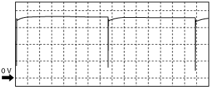
Inspection Using an Oscilloscope (reference)
|
Oscilloscope setting: |
Terminal |
|||||
|---|---|---|---|---|---|---|
|
Ignition |
Shift lever position |
Vehicle speed |
Corner ultrasonic sensor (LH) |
Ultrasonic sensor (LH) |
Ultrasonic sensor (RH) |
Corner ultrasonic sensor (RH) |
|
ON (engine off or on)
|
R position
|
0—15 km/h {0—9.3 mph} or less
|
E—B
|
I—B
|
K—B
|
G—B
|
am6zzw00006971
|