 |
am2zzn00001862
MULTIPLEX COMMUNICATION SYSTEM
id100000001400
Outline
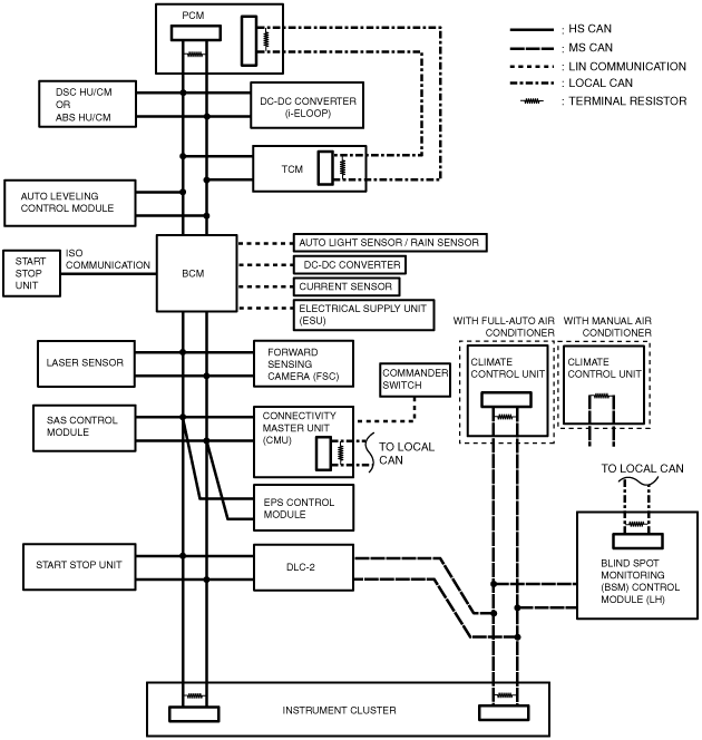
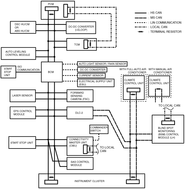
System Wiring Diagram
CAN/LIN communication/ISO communication/local CAN (L.H.D. (SKYACTIV-G 1.5))
am2zzn00001862
|
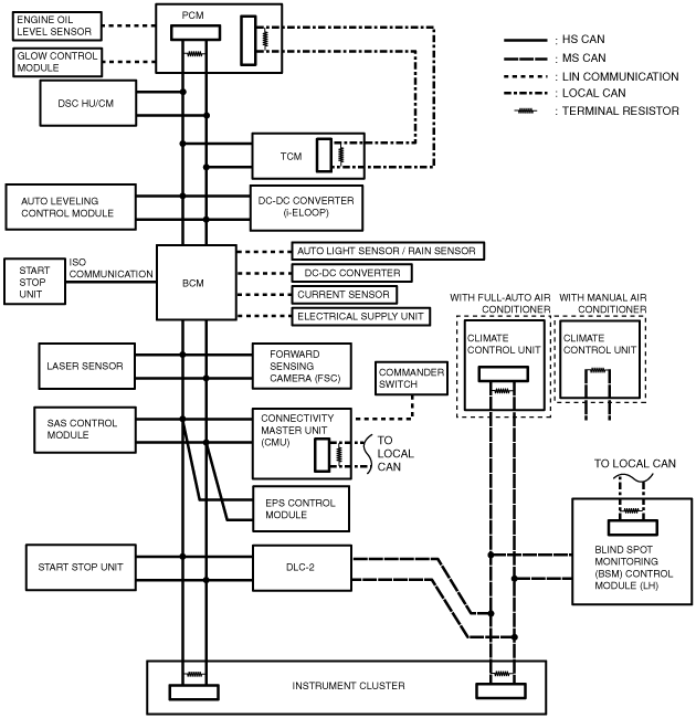
CAN/LIN communication/ISO communication/local CAN (R.H.D. (SKYACTIV-G 1.3, SKYACTIV-G 1.5))
am2zzn00001625
|
CAN/LIN communication/ISO communication/local CAN (SKYACTIV-D 1.5)
am2zzn00001863
|
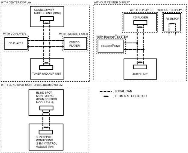
Local CAN
am2zzn00001627
|
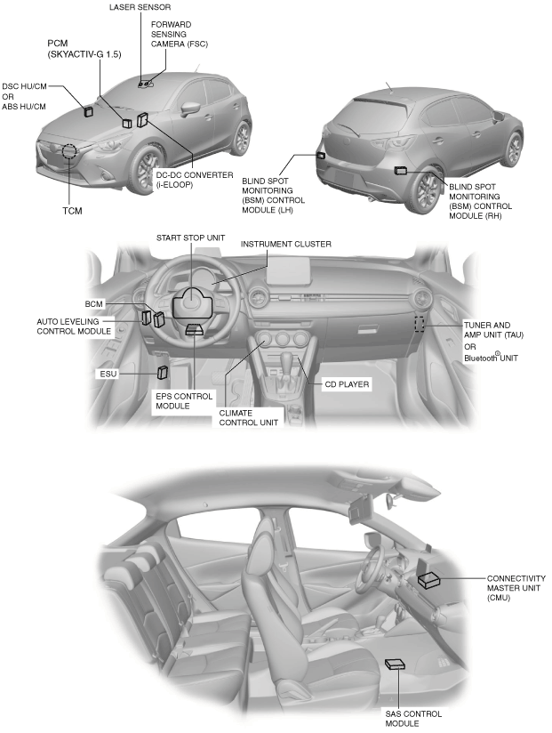
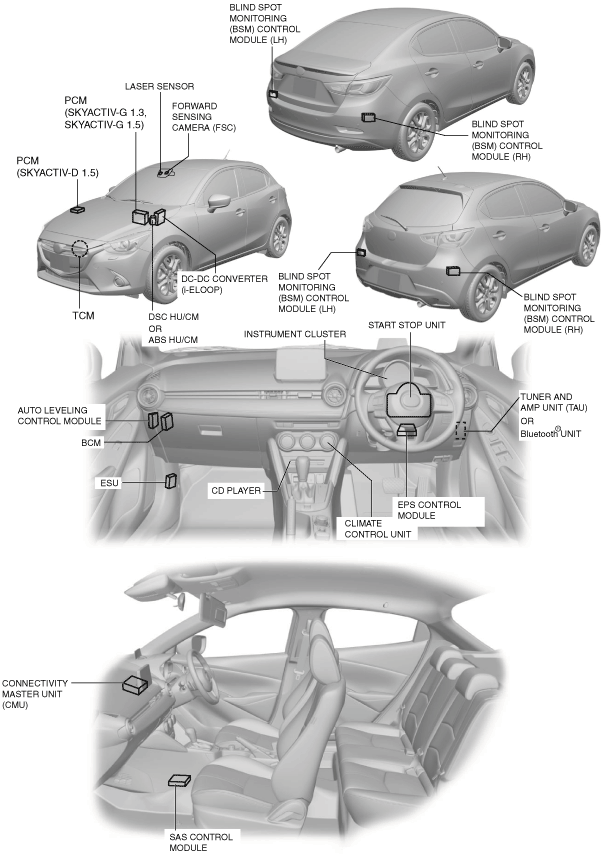
Structural view
L.H.D.
am2zzn00001864
|
R.H.D.
am2zzn00001865
|
Function
CAN (controller area network) system
HS-CAN communication table
|
Signal |
CAN system related module |
|||||||||||||
|---|---|---|---|---|---|---|---|---|---|---|---|---|---|---|
|
PCM |
TCM |
Auto leveling control module |
Laser sensor |
DSC HU/CM*2 |
ABS HU/CM*3 |
EPS control module |
BCM |
FSC |
Instrument cluster |
Start stop unit |
SAS control module |
DC-DC converter (i-ELOOP) |
Connectivity master unit |
|
|
Acceleration status
|
–
|
–
|
–
|
–
|
IN
|
IN
|
–
|
–
|
–
|
–
|
–
|
OUT
|
–
|
–
|
|
Accelerator pedal opening angle information
|
OUT
|
–
|
–
|
–
|
IN
|
IN
|
–
|
–
|
IN
|
IN
|
–
|
IN
|
–
|
IN
|
|
A/C operation request
|
IN
|
–
|
–
|
–
|
–
|
–
|
–
|
–
|
–
|
OUT
|
–
|
–
|
–
|
IN
|
|
Air bag/front seat belt pre-tensioner system warning light on request
|
–
|
–
|
–
|
–
|
–
|
–
|
–
|
–
|
–
|
IN
|
–
|
OUT
|
–
|
IN
|
|
Air bag system-related information
|
–
|
–
|
–
|
–
|
–
|
–
|
–
|
–
|
–
|
IN
|
–
|
OUT
|
–
|
IN
|
|
Air bag system warning buzzer status
|
–
|
–
|
–
|
–
|
–
|
–
|
–
|
–
|
–
|
IN
|
–
|
OUT
|
–
|
IN
|
|
Ambient temperature
|
OUT
|
IN
|
–
|
IN
|
IN
|
–
|
–
|
IN
|
–
|
IN
|
–
|
IN
|
–
|
IN
|
|
IN
|
IN
|
IN
|
IN
|
IN
|
–
|
IN
|
IN
|
–
|
OUT
|
IN
|
IN
|
–
|
IN
|
|
|
Back-up lights ON (MTX)
|
OUT
|
–
|
–
|
–
|
IN
|
–
|
–
|
–
|
IN
|
IN
|
–
|
IN
|
–
|
IN
|
|
Back-up light on request
|
–
|
–
|
IN
|
IN
|
IN
|
–
|
–
|
IN
|
–
|
OUT
|
–
|
–
|
–
|
IN
|
|
Battery discharge suppression status
|
–
|
–
|
–
|
–
|
–
|
–
|
–
|
OUT
|
–
|
IN
|
–
|
–
|
–
|
–
|
|
Battery regeneration status
|
OUT
|
–
|
–
|
–
|
–
|
–
|
–
|
–
|
–
|
IN
|
–
|
–
|
–
|
IN
|
|
BCM personalization-related information
|
–
|
–
|
–
|
–
|
–
|
–
|
–
|
IN
|
–
|
–
|
–
|
–
|
–
|
OUT
|
|
–
|
–
|
–
|
–
|
–
|
–
|
–
|
OUT
|
–
|
–
|
–
|
–
|
–
|
IN
|
|
|
Blind spot monitoring (BSM) system personalization-related information
|
–
|
–
|
–
|
–
|
–
|
–
|
–
|
–
|
–
|
IN
|
–
|
–
|
–
|
OUT
|
|
–
|
–
|
–
|
–
|
–
|
–
|
–
|
–
|
–
|
OUT
|
–
|
–
|
–
|
IN
|
|
|
Blind spot monitoring (BSM) system-related information
|
–
|
–
|
–
|
–
|
–
|
–
|
–
|
–
|
–
|
OUT
|
–
|
–
|
–
|
IN
|
|
IN
|
–
|
–
|
–
|
–
|
–
|
–
|
OUT
|
–
|
–
|
–
|
–
|
–
|
–
|
|
|
Blower relay status
|
–
|
–
|
–
|
–
|
–
|
–
|
–
|
OUT
|
–
|
IN
|
–
|
–
|
–
|
–
|
|
Blower speed
|
–
|
–
|
–
|
–
|
–
|
–
|
–
|
–
|
–
|
OUT
|
–
|
–
|
–
|
IN
|
|
Brake fluid level
|
–
|
–
|
–
|
–
|
–
|
–
|
–
|
OUT
|
–
|
IN
|
–
|
–
|
–
|
IN
|
|
Brake light status
|
–
|
–
|
–
|
–
|
IN
|
–
|
–
|
OUT
|
–
|
IN
|
–
|
–
|
–
|
IN
|
|
Brake switch malfunction determination
|
OUT
|
–
|
–
|
–
|
–
|
–
|
–
|
–
|
–
|
IN
|
–
|
–
|
–
|
IN
|
|
Brake switch (No.1)
|
OUT
|
IN
|
–
|
–
|
IN
|
–
|
–
|
IN
|
IN
|
IN
|
–
|
–
|
–
|
IN
|
|
Brake switch (No.2)
|
OUT
|
IN
|
–
|
–
|
–
|
–
|
–
|
–
|
IN
|
IN
|
IN
|
IN
|
–
|
IN
|
|
Charging system warning light on request
|
OUT
|
–
|
–
|
–
|
–
|
–
|
–
|
IN
|
–
|
IN
|
–
|
–
|
–
|
IN
|
|
Check engine light on request
|
OUT
|
–
|
–
|
–
|
–
|
–
|
–
|
–
|
–
|
IN
|
–
|
–
|
–
|
IN
|
|
Cluster switch status
|
–
|
–
|
IN
|
–
|
–
|
–
|
–
|
–
|
IN
|
OUT
|
–
|
–
|
–
|
–
|
|
Clutch status
|
OUT
|
–
|
–
|
–
|
–
|
–
|
–
|
–
|
–
|
–
|
–
|
–
|
–
|
IN
|
|
Collision detection (front, side, roll over)
|
IN
|
–
|
–
|
–
|
IN
|
–
|
–
|
IN
|
–
|
–
|
–
|
OUT
|
–
|
IN
|
|
Combiner auto-dimming level
|
–
|
–
|
–
|
–
|
–
|
–
|
–
|
–
|
–
|
IN
|
–
|
–
|
–
|
OUT
|
|
Combiner dimming switching
|
–
|
–
|
–
|
–
|
–
|
–
|
–
|
–
|
–
|
IN
|
–
|
–
|
–
|
OUT
|
|
Combiner manual-dimming level
|
–
|
–
|
–
|
–
|
–
|
–
|
–
|
–
|
–
|
IN
|
–
|
–
|
–
|
OUT
|
|
Combiner open/close angle
|
–
|
–
|
–
|
–
|
–
|
–
|
–
|
–
|
–
|
IN
|
–
|
–
|
–
|
OUT
|
|
Cranking
|
IN
|
–
|
–
|
–
|
–
|
–
|
–
|
IN
|
–
|
IN
|
OUT
|
–
|
–
|
–
|
|
Cranking time
|
OUT
|
–
|
–
|
–
|
–
|
–
|
–
|
–
|
–
|
–
|
IN
|
–
|
–
|
IN
|
|
Cruise control switch
|
OUT
|
–
|
–
|
–
|
–
|
–
|
–
|
–
|
–
|
IN
|
IN
|
–
|
–
|
IN
|
|
IN
|
–
|
–
|
–
|
–
|
–
|
–
|
–
|
–
|
OUT
|
–
|
–
|
–
|
IN
|
|
|
IN
|
IN
|
–
|
–
|
–
|
–
|
–
|
–
|
–
|
–
|
OUT
|
–
|
–
|
–
|
|
|
DC-DC converter status
|
IN
|
–
|
–
|
–
|
–
|
–
|
–
|
OUT
|
–
|
–
|
–
|
–
|
–
|
–
|
|
Dimmer cancel
|
–
|
–
|
–
|
–
|
–
|
–
|
–
|
–
|
–
|
OUT
|
IN
|
–
|
–
|
IN
|
|
Door lock/unlock status
|
–
|
–
|
–
|
–
|
–
|
–
|
–
|
–
|
–
|
–
|
OUT
|
–
|
–
|
IN
|
|
Door opening/closing condition
|
IN
|
–
|
–
|
–
|
–
|
–
|
–
|
OUT
|
–
|
IN
|
IN
|
–
|
IN
|
IN
|
|
DPF indicator light on request
|
OUT*1
|
–
|
–
|
–
|
–
|
–
|
–
|
–
|
–
|
IN
|
–
|
–
|
–
|
IN
|
|
Driver's buckle switch status
|
IN
|
–
|
–
|
–
|
–
|
–
|
–
|
IN
|
–
|
IN
|
IN
|
OUT
|
–
|
IN
|
|
Driving condition
|
IN
|
–
|
IN
|
IN
|
IN
|
IN
|
IN
|
IN
|
–
|
OUT
|
IN
|
IN
|
–
|
IN
|
|
DSC system-related information
|
OUT
|
–
|
–
|
–
|
IN
|
–
|
–
|
–
|
–
|
–
|
–
|
–
|
–
|
–
|
|
IN
|
IN
|
–
|
IN
|
OUT
|
–
|
IN
|
IN
|
IN
|
IN
|
–
|
IN
|
–
|
IN
|
|
|
DSC OFF switch status
|
–
|
–
|
–
|
–
|
IN
|
–
|
–
|
–
|
–
|
OUT
|
–
|
–
|
–
|
–
|
|
Electric AT oil pump-related (i-stop)
|
IN
|
OUT
|
–
|
–
|
–
|
–
|
–
|
–
|
–
|
–
|
–
|
–
|
–
|
–
|
|
Engine coolant temperature
|
OUT
|
–
|
–
|
–
|
–
|
–
|
–
|
IN
|
–
|
IN
|
–
|
–
|
–
|
IN
|
|
Engine displacement
|
OUT
|
IN
|
–
|
–
|
IN
|
–
|
IN
|
–
|
–
|
IN
|
–
|
–
|
–
|
IN
|
|
Engine rotation speed
|
OUT
|
–
|
–
|
–
|
IN
|
–
|
IN
|
IN
|
IN
|
IN
|
IN
|
IN
|
–
|
IN
|
|
Engine status
|
OUT
|
IN
|
–
|
–
|
IN
|
–
|
IN
|
IN
|
–
|
IN
|
IN
|
–
|
–
|
IN
|
|
Engine stop request
|
IN
|
–
|
–
|
–
|
–
|
–
|
–
|
–
|
–
|
OUT
|
–
|
–
|
–
|
IN
|
|
Engine switch status
|
–
|
–
|
IN
|
–
|
–
|
–
|
IN
|
IN
|
IN
|
OUT
|
–
|
–
|
–
|
IN
|
|
IN
|
IN
|
–
|
–
|
–
|
–
|
–
|
IN
|
–
|
IN
|
OUT
|
–
|
–
|
IN
|
|
|
Engine torque
|
OUT
|
–
|
–
|
–
|
–
|
–
|
–
|
IN
|
–
|
–
|
–
|
–
|
–
|
–
|
|
EPS status
|
IN
|
–
|
–
|
–
|
–
|
–
|
OUT
|
–
|
–
|
IN
|
–
|
–
|
–
|
IN
|
|
Forward sensing camera (FSC) personalization-related information
|
–
|
–
|
–
|
–
|
–
|
–
|
–
|
–
|
IN
|
–
|
–
|
–
|
–
|
OUT
|
|
–
|
–
|
–
|
–
|
–
|
–
|
–
|
–
|
OUT
|
–
|
–
|
–
|
–
|
IN
|
|
|
Front fog light information
|
–
|
–
|
–
|
–
|
–
|
–
|
–
|
OUT
|
IN
|
IN
|
–
|
–
|
–
|
IN
|
|
Front fog light switch position
|
–
|
–
|
–
|
–
|
–
|
–
|
–
|
IN
|
–
|
–
|
OUT
|
–
|
–
|
–
|
|
Fuel cut request
|
IN
|
–
|
–
|
–
|
IN
|
–
|
–
|
IN
|
–
|
IN
|
–
|
OUT
|
IN
|
IN
|
|
Fuel economy information reset request
|
–
|
–
|
–
|
–
|
–
|
–
|
–
|
–
|
–
|
IN
|
–
|
–
|
–
|
OUT
|
|
Fuel injection amount
|
OUT
|
–
|
–
|
–
|
–
|
–
|
–
|
–
|
–
|
IN
|
–
|
–
|
–
|
IN
|
|
Fuel-level sensor-related information
|
–
|
–
|
–
|
–
|
–
|
–
|
–
|
OUT
|
–
|
IN
|
–
|
–
|
–
|
–
|
|
Fuel tank level
|
IN
|
–
|
–
|
–
|
–
|
–
|
–
|
–
|
–
|
OUT
|
–
|
–
|
–
|
IN
|
|
Gear position
|
OUT
|
–
|
–
|
–
|
–
|
–
|
–
|
–
|
–
|
IN
|
–
|
IN
|
–
|
IN
|
|
–
|
OUT
|
–
|
–
|
IN
|
IN
|
–
|
IN
|
IN
|
IN
|
IN
|
IN
|
–
|
IN
|
|
|
Global central configuration
|
IN
|
IN
|
IN
|
IN
|
IN
|
–
|
IN
|
IN
|
–
|
OUT
|
IN
|
IN
|
–
|
IN
|
|
Global central configuration error
|
OUT
|
–
|
–
|
–
|
–
|
–
|
–
|
–
|
–
|
IN
|
–
|
–
|
–
|
IN
|
|
Glow indicator light on request
|
OUT*1
|
–
|
–
|
–
|
–
|
–
|
–
|
–
|
–
|
IN
|
–
|
–
|
–
|
IN
|
|
Glow indicator light voltage
|
IN*1
|
–
|
–
|
–
|
–
|
–
|
–
|
–
|
–
|
OUT
|
–
|
–
|
–
|
–
|
|
Hazard warning switch information
|
–
|
–
|
–
|
–
|
–
|
–
|
–
|
IN
|
IN
|
IN
|
OUT
|
–
|
–
|
–
|
|
Headlight high-beam indicator light
|
–
|
–
|
–
|
–
|
–
|
–
|
–
|
OUT
|
IN
|
IN
|
–
|
–
|
–
|
IN
|
|
Headlight status
|
IN
|
–
|
IN
|
–
|
–
|
–
|
–
|
OUT
|
IN
|
IN
|
–
|
–
|
–
|
IN
|
|
Headlight warning request
|
–
|
–
|
–
|
–
|
–
|
–
|
–
|
OUT
|
–
|
IN
|
–
|
–
|
–
|
IN
|
|
High-beam control system personalization-related information
|
–
|
–
|
–
|
–
|
–
|
–
|
–
|
–
|
IN
|
–
|
–
|
–
|
–
|
OUT
|
|
–
|
–
|
–
|
–
|
–
|
–
|
–
|
–
|
OUT
|
–
|
–
|
–
|
–
|
IN
|
|
|
High-beam on request
|
–
|
–
|
–
|
–
|
–
|
–
|
–
|
IN
|
OUT
|
–
|
–
|
–
|
–
|
–
|
|
Horn sound request
|
–
|
–
|
–
|
–
|
–
|
–
|
–
|
IN
|
–
|
–
|
OUT
|
–
|
–
|
–
|
|
i-ELOOP-related information
|
OUT
|
IN
|
–
|
–
|
–
|
–
|
–
|
–
|
–
|
IN
|
–
|
–
|
IN
|
IN
|
|
IN
|
IN
|
–
|
–
|
–
|
–
|
–
|
IN
|
–
|
IN
|
–
|
–
|
OUT
|
IN
|
|
|
Immobilizer system-related information
|
OUT
|
–
|
–
|
–
|
–
|
–
|
–
|
–
|
–
|
–
|
IN
|
–
|
–
|
–
|
|
IN
|
–
|
–
|
–
|
–
|
–
|
–
|
–
|
–
|
–
|
OUT
|
–
|
–
|
–
|
|
|
Instrument cluster personalization-related information
|
–
|
–
|
–
|
–
|
–
|
–
|
–
|
IN
|
IN
|
IN
|
IN
|
–
|
–
|
OUT
|
|
–
|
–
|
–
|
–
|
–
|
–
|
–
|
–
|
–
|
–
|
OUT
|
–
|
–
|
IN
|
|
|
–
|
–
|
–
|
–
|
–
|
–
|
–
|
–
|
OUT
|
–
|
–
|
–
|
–
|
IN
|
|
|
–
|
–
|
–
|
–
|
–
|
–
|
–
|
OUT
|
–
|
–
|
–
|
–
|
–
|
IN
|
|
|
–
|
–
|
–
|
–
|
–
|
–
|
–
|
–
|
–
|
OUT
|
–
|
–
|
–
|
IN
|
|
|
i-stop OFF switch status
|
IN
|
–
|
–
|
–
|
–
|
–
|
–
|
–
|
–
|
OUT
|
–
|
–
|
–
|
–
|
|
i-stop-related information
|
OUT
|
–
|
–
|
–
|
–
|
–
|
–
|
–
|
–
|
IN
|
–
|
–
|
–
|
IN
|
|
IN
|
–
|
–
|
–
|
–
|
–
|
–
|
–
|
–
|
–
|
OUT
|
–
|
–
|
–
|
|
|
IN
|
IN
|
–
|
–
|
OUT
|
–
|
–
|
–
|
–
|
–
|
–
|
–
|
–
|
–
|
|
|
i-stop warning light (amber)/i-stop indicator light (green) on request
|
OUT
|
IN
|
–
|
–
|
–
|
–
|
–
|
–
|
–
|
IN
|
IN
|
–
|
–
|
IN
|
|
Keyless warning alarm activation request
|
–
|
–
|
–
|
–
|
–
|
–
|
–
|
–
|
–
|
IN
|
OUT
|
–
|
–
|
IN
|
|
KEY warning light (amber)/KEY indicator light (green) on request
|
–
|
–
|
–
|
–
|
–
|
–
|
–
|
OUT
|
–
|
IN
|
–
|
–
|
–
|
IN
|
|
–
|
–
|
–
|
–
|
–
|
–
|
–
|
–
|
–
|
IN
|
OUT
|
–
|
–
|
IN
|
|
|
Laser sensor-related information
|
IN
|
–
|
–
|
OUT
|
–
|
–
|
–
|
–
|
–
|
–
|
–
|
–
|
–
|
IN
|
|
LED headlight warning light on request
|
–
|
–
|
OUT
|
–
|
–
|
–
|
–
|
–
|
–
|
IN
|
–
|
–
|
–
|
IN
|
|
Light switch information
|
–
|
–
|
–
|
–
|
–
|
–
|
–
|
IN
|
IN
|
IN
|
OUT
|
–
|
–
|
–
|
|
Maintenance monitor-related information
|
–
|
–
|
–
|
–
|
–
|
–
|
–
|
–
|
–
|
IN
|
–
|
–
|
–
|
OUT
|
|
Master warning light indication request
|
–
|
–
|
–
|
–
|
–
|
–
|
–
|
–
|
–
|
IN
|
–
|
–
|
–
|
OUT
|
|
Manual shift control
|
–
|
IN
|
–
|
–
|
–
|
–
|
–
|
–
|
–
|
OUT
|
–
|
–
|
–
|
–
|
|
–
|
OUT
|
–
|
–
|
IN
|
IN
|
–
|
–
|
–
|
–
|
–
|
–
|
–
|
–
|
|
|
Manual shift inhibit flash command
|
–
|
OUT
|
–
|
–
|
–
|
–
|
–
|
–
|
–
|
IN
|
–
|
–
|
–
|
IN
|
|
Neutral switch
|
OUT
|
IN
|
–
|
–
|
–
|
–
|
–
|
–
|
–
|
IN
|
IN
|
IN
|
–
|
IN
|
|
Oil level warning
|
OUT
|
–
|
–
|
–
|
–
|
–
|
–
|
–
|
–
|
IN
|
–
|
–
|
–
|
IN
|
|
Oil level warning limit
|
OUT
|
–
|
–
|
–
|
–
|
–
|
–
|
–
|
–
|
–
|
–
|
–
|
–
|
IN
|
|
Oil warning light on request
|
OUT
|
–
|
–
|
–
|
–
|
–
|
–
|
–
|
–
|
IN
|
–
|
–
|
–
|
–
|
|
Panel light
|
–
|
–
|
–
|
–
|
–
|
–
|
–
|
–
|
–
|
OUT
|
IN
|
–
|
–
|
IN
|
|
Panel light on request
|
–
|
–
|
–
|
–
|
–
|
–
|
–
|
–
|
–
|
OUT
|
–
|
–
|
–
|
IN
|
|
Parking brake status
|
IN
|
IN
|
–
|
–
|
IN
|
IN
|
–
|
IN
|
–
|
OUT
|
–
|
–
|
–
|
IN
|
|
Passenger's buckle switch status
|
–
|
–
|
–
|
–
|
–
|
–
|
–
|
–
|
–
|
IN
|
–
|
OUT
|
–
|
IN
|
|
Passing switch information
|
–
|
–
|
–
|
–
|
–
|
–
|
–
|
IN
|
IN
|
IN
|
OUT
|
–
|
–
|
–
|
|
Power consumption
|
IN
|
–
|
–
|
–
|
–
|
–
|
OUT
|
–
|
–
|
–
|
–
|
–
|
–
|
IN
|
|
Prevention of brake override system unnecessary operation
|
OUT
|
–
|
–
|
–
|
–
|
–
|
–
|
IN
|
–
|
IN
|
–
|
–
|
–
|
IN
|
|
Priority recirculate request
|
OUT
|
–
|
–
|
–
|
–
|
–
|
–
|
–
|
–
|
IN
|
–
|
–
|
–
|
–
|
|
Rear fog indicator light information
|
–
|
–
|
–
|
–
|
–
|
–
|
–
|
OUT
|
–
|
IN
|
–
|
–
|
–
|
IN
|
|
Rear fog light switch position
|
–
|
–
|
–
|
–
|
–
|
–
|
–
|
IN
|
–
|
–
|
OUT
|
–
|
–
|
–
|
|
Rear washer switch position
|
–
|
–
|
–
|
–
|
–
|
–
|
–
|
IN
|
–
|
–
|
OUT
|
–
|
–
|
–
|
|
Rear window defogger information
|
IN
|
–
|
–
|
–
|
–
|
–
|
–
|
OUT
|
–
|
IN
|
–
|
–
|
–
|
IN
|
|
Rear window defogger operation request
|
–
|
–
|
–
|
–
|
–
|
–
|
–
|
IN
|
–
|
OUT
|
–
|
–
|
–
|
–
|
|
Rear wiper low speed status
|
–
|
–
|
–
|
–
|
–
|
–
|
–
|
OUT
|
IN
|
IN
|
–
|
–
|
–
|
IN
|
|
Rear wiper switch position
|
–
|
IN
|
–
|
–
|
–
|
–
|
–
|
IN
|
–
|
–
|
OUT
|
–
|
–
|
–
|
|
Rolling counter
|
–
|
–
|
–
|
–
|
IN
|
IN
|
–
|
–
|
–
|
–
|
–
|
OUT
|
–
|
–
|
|
ROOM fuse status
|
–
|
IN
|
–
|
–
|
–
|
–
|
–
|
–
|
IN
|
OUT
|
–
|
–
|
IN
|
–
|
|
–
|
–
|
–
|
–
|
–
|
–
|
–
|
OUT
|
–
|
IN
|
–
|
–
|
–
|
IN
|
|
|
Seat belt status
|
–
|
–
|
–
|
–
|
–
|
–
|
–
|
OUT
|
–
|
IN
|
–
|
–
|
–
|
IN
|
|
Security indicator light on request
|
–
|
–
|
–
|
–
|
–
|
–
|
–
|
–
|
–
|
IN
|
OUT
|
–
|
–
|
IN
|
|
Selector lever position
|
–
|
OUT
|
–
|
–
|
–
|
–
|
–
|
–
|
–
|
IN
|
–
|
–
|
–
|
IN
|
|
IN
|
OUT
|
–
|
–
|
–
|
–
|
–
|
–
|
–
|
–
|
–
|
–
|
–
|
–
|
|
|
Shift indicator light
|
OUT
|
–
|
–
|
–
|
–
|
–
|
–
|
–
|
–
|
IN
|
–
|
–
|
–
|
IN
|
|
Smart City Brake Support (SCBS)-related information
|
–
|
–
|
–
|
–
|
–
|
–
|
–
|
–
|
–
|
IN
|
–
|
–
|
–
|
OUT
|
|
Starter relay status
|
OUT
|
–
|
–
|
–
|
–
|
–
|
–
|
–
|
–
|
–
|
IN
|
–
|
–
|
–
|
|
Start stop unit personalization-related information
|
–
|
–
|
–
|
–
|
–
|
–
|
–
|
–
|
–
|
–
|
OUT
|
–
|
–
|
IN
|
|
–
|
–
|
–
|
–
|
–
|
–
|
–
|
–
|
–
|
–
|
IN
|
–
|
–
|
OUT
|
|
|
Steering angle (absolute steering angle)
|
–
|
–
|
–
|
–
|
–
|
–
|
IN
|
–
|
–
|
–
|
OUT
|
–
|
–
|
–
|
|
Steering angle condition
|
IN
|
–
|
–
|
IN
|
–
|
–
|
OUT
|
–
|
–
|
–
|
–
|
–
|
–
|
IN
|
|
IN
|
IN
|
IN
|
IN
|
IN
|
–
|
IN
|
IN
|
–
|
OUT
|
IN
|
IN
|
–
|
IN
|
|
|
Steering angle (estimated absolute steering angle)
|
IN
|
IN
|
IN
|
IN
|
IN
|
–
|
OUT
|
–
|
IN
|
IN
|
IN
|
IN
|
–
|
IN
|
|
Steering lock-related information
|
–
|
–
|
–
|
–
|
–
|
–
|
–
|
–
|
–
|
IN
|
OUT
|
–
|
–
|
IN
|
|
Steering shift switch
|
–
|
IN
|
–
|
–
|
–
|
–
|
–
|
–
|
–
|
–
|
OUT
|
–
|
–
|
–
|
|
Supply voltage
|
IN
|
–
|
IN
|
IN
|
IN
|
–
|
IN
|
IN
|
–
|
OUT
|
IN
|
IN
|
–
|
IN
|
|
Target gear position
|
–
|
OUT
|
–
|
–
|
IN
|
–
|
–
|
–
|
–
|
IN
|
–
|
–
|
–
|
IN
|
|
Temperature control dial status
|
IN
|
–
|
–
|
–
|
–
|
–
|
–
|
–
|
–
|
OUT
|
–
|
–
|
–
|
IN
|
|
TNS condition
|
–
|
–
|
–
|
–
|
–
|
–
|
–
|
OUT
|
–
|
IN
|
IN
|
–
|
–
|
IN
|
|
Transmission information
|
OUT
|
IN
|
–
|
–
|
–
|
–
|
–
|
–
|
–
|
IN
|
IN
|
–
|
–
|
–
|
|
Traveled distance
|
OUT
|
–
|
–
|
–
|
–
|
–
|
–
|
–
|
–
|
IN
|
–
|
–
|
–
|
IN
|
|
Tuner and amplifier unit (TAU) communication status
|
–
|
–
|
–
|
–
|
–
|
–
|
–
|
–
|
–
|
IN
|
–
|
–
|
–
|
OUT
|
|
Turn signal/hazard warning light on request
|
–
|
–
|
–
|
–
|
–
|
–
|
–
|
OUT
|
IN
|
IN
|
–
|
–
|
–
|
IN
|
|
Turn switch position
|
–
|
IN
|
–
|
–
|
–
|
–
|
–
|
IN
|
IN
|
IN
|
OUT
|
–
|
–
|
–
|
|
Vehicle specification information
|
IN
|
IN
|
IN
|
IN
|
IN
|
–
|
IN
|
IN
|
–
|
OUT
|
IN
|
IN
|
–
|
IN
|
|
Vehicle speed
|
IN
|
–
|
–
|
IN
|
OUT
|
–
|
IN
|
–
|
IN
|
IN
|
IN
|
–
|
–
|
–
|
|
OUT
|
–
|
IN
|
–
|
IN
|
IN
|
IN
|
IN
|
IN
|
IN
|
IN
|
IN
|
–
|
IN
|
|
|
Warning guidance-related information
|
–
|
–
|
–
|
–
|
–
|
–
|
–
|
–
|
–
|
IN
|
–
|
–
|
–
|
OUT
|
|
Washer level sensor status
|
–
|
–
|
–
|
–
|
–
|
–
|
–
|
OUT
|
–
|
IN
|
–
|
–
|
–
|
IN
|
|
Wheel speed
|
IN
|
IN
|
–
|
IN
|
OUT
|
–
|
IN
|
IN
|
IN
|
IN
|
IN
|
IN
|
–
|
IN
|
|
Windshield washer switch position
|
–
|
–
|
–
|
IN
|
–
|
–
|
–
|
IN
|
–
|
IN
|
OUT
|
–
|
–
|
–
|
|
Windshield wiper (INT) volume position
|
–
|
–
|
–
|
–
|
–
|
–
|
–
|
IN
|
–
|
–
|
OUT
|
–
|
–
|
–
|
|
Windshield wiper operation request for rain light sensor
|
–
|
–
|
–
|
–
|
–
|
–
|
–
|
OUT
|
IN
|
–
|
–
|
–
|
–
|
IN
|
|
Windshield wiper operation status
|
IN
|
–
|
–
|
IN
|
IN
|
–
|
–
|
OUT
|
IN
|
IN
|
–
|
–
|
–
|
IN
|
|
Windshield wiper switch position
|
–
|
IN
|
–
|
IN
|
–
|
–
|
–
|
IN
|
–
|
–
|
OUT
|
–
|
–
|
–
|
|
Yaw rate
|
–
|
–
|
–
|
–
|
IN
|
IN
|
–
|
–
|
–
|
–
|
–
|
OUT
|
–
|
–
|
|
IN
|
IN
|
–
|
IN
|
OUT
|
–
|
IN
|
IN
|
IN
|
IN
|
–
|
–
|
–
|
IN
|
|
MS-CAN communication table
|
Signal |
CAN system related module |
||
|---|---|---|---|
|
Climate control unit |
Instrument cluster |
Blind spot monitoring (BSM) control module (LH) |
|
|
A/C operation request
|
OUT
|
IN
|
–
|
|
Air bag/front seat belt pre-tensioner system warning light on request
|
IN
|
OUT
|
–
|
|
Ambient temperature
|
IN
|
OUT
|
IN
|
|
Back-up light on request
|
–
|
OUT
|
IN
|
|
Blind spot monitoring (BSM) system personalization-related information
|
–
|
OUT
|
IN
|
|
–
|
IN
|
OUT
|
|
|
Blind spot monitoring (BSM) system-related information
|
–
|
IN
|
OUT
|
|
–
|
OUT
|
IN
|
|
|
Blower relay status
|
IN
|
OUT
|
–
|
|
Blower speed
|
OUT
|
IN
|
–
|
|
Cluster switch status
|
–
|
OUT
|
IN
|
|
Cranking
|
IN
|
OUT
|
–
|
|
Dimmer cancel
|
IN
|
OUT
|
IN
|
|
Driver information system information
|
IN
|
OUT
|
–
|
|
Driving condition
|
IN
|
OUT
|
IN
|
|
Engine coolant temperature
|
IN
|
OUT
|
–
|
|
Engine displacement
|
IN
|
OUT
|
–
|
|
Engine rotation speed
|
IN
|
OUT
|
–
|
|
Engine status
|
IN
|
OUT
|
IN
|
|
Engine stop request
|
OUT
|
IN
|
–
|
|
Engine switch condition
|
IN
|
OUT
|
IN
|
|
Gear position
|
–
|
OUT
|
IN
|
|
Global central configuration
|
IN
|
OUT
|
IN
|
|
Instrument cluster personalization-related information
|
–
|
OUT
|
IN
|
|
–
|
IN
|
OUT
|
|
|
Panel light
|
IN
|
OUT
|
–
|
|
Panel light on request
|
IN
|
OUT
|
IN
|
|
Priority recirculate request
|
IN
|
OUT
|
–
|
|
Rear window defogger information
|
IN
|
OUT
|
–
|
|
Rear window defogger operation request
|
OUT
|
IN
|
–
|
|
ROOM fuse status
|
IN
|
OUT
|
–
|
|
Steering angle condition
|
IN
|
OUT
|
IN
|
|
Steering angle (estimated absolute steering angle)
|
–
|
OUT
|
IN
|
|
Supply voltage
|
IN
|
OUT
|
IN
|
|
Temperature control dial status
|
OUT
|
IN
|
–
|
|
Traveled distance
|
IN
|
OUT
|
IN
|
|
Turn switch status
|
–
|
OUT
|
IN
|
|
Vehicle speed
|
IN
|
OUT
|
IN
|
|
Vehicle specification information
|
IN
|
OUT
|
IN
|
|
Windshield defroster
|
OUT
|
IN
|
–
|
|
Windshield wiper operation status
|
IN
|
OUT
|
–
|
|
Yaw rate
|
–
|
OUT
|
IN
|
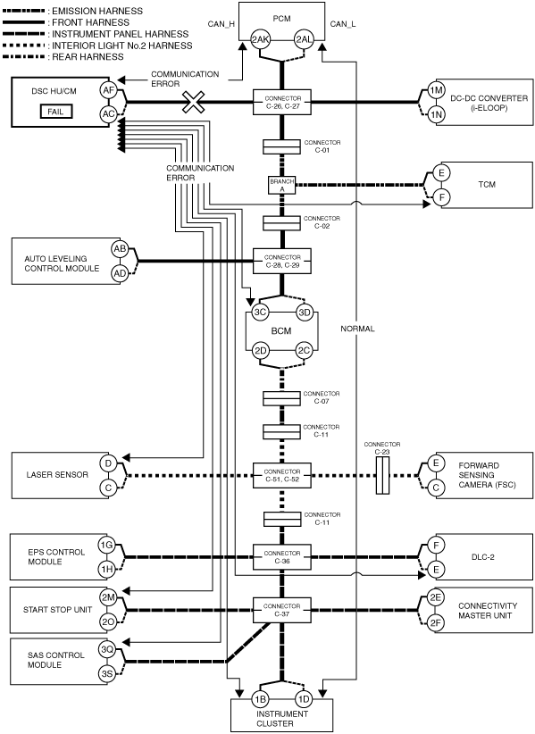
Malfunction diagnosis procedure
Ex.) Open circuit location determination procedure
1. Verify the CAN system-related module DTCs and the failed module using the Mazda Modular Diagnostic System (M-MDS).
|
DTC output module |
Mazda Modular Diagnostic System (M-MDS) display |
Output DTC |
|---|---|---|
|
PCM
|
PCM
|
U0121:00
|
|
TCM
|
TCM
|
U0121:00
|
|
BCM
|
BCM
|
U0121:00
|
|
Laser sensor
|
SCBS
|
U0121:00
|
|
Forward sensing camera (FSC)
|
FSC
|
U0121:00
|
|
Connectivity master unit (CMU)
|
CMU
|
U0121:00
|
|
EPS control module
|
EPS
|
U0121:00
|
|
Start stop unit
|
SSU
|
U0121:00
|
|
Instrument cluster
|
IC
|
U0121:00
|
|
Module |
Fail display |
|---|---|
|
DSC HU/CM
|
×
|
2. As a result of DTC verification, only DTCs related to DSC HU/CM and communication errors are output and the DSC HU/CM is indicated as failed, therefore there could be a malfunction in the DSC HU/CM or in the wiring harness between connector C-26, C-27 and DSC HU/CM.
am2zzn00002176
|
Local CAN
LIN communication
ISO communication
Construction
CAN
Local CAN
LIN communication
ISO communication