SERVICE CAUTIONS
id000000000200
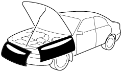
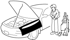
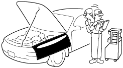
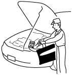
Protection of the Vehicle
• Always be sure to cover fenders, seats and floor areas before starting work.
Preparation of Tools and Measuring Equipment
• Be sure that all necessary tools and measuring equipment are available before starting any work.
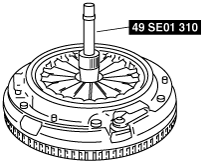
Special Service Tools
• Use special service tools or equivalent when they are required.
Disconnection of the Negative Battery Cable
• Before beginning any work, turn the ignition switch to LOCK position, then disconnect the negative battery cable and wait for more than 1 min. to allow the backup power supply of the SAS control module to deplete its stored power. Disconnecting the battery cable will delete the memories of the clock, audio, and DTCs, etc. Therefore, it is necessary to verify those memories before disconnecting the cable.
• If the battery had been disconnected during vehicle maintenance or for other reasons, the window will not fully close automatically. Carry out the power window each switch initial setting. (See
POWER WINDOW SYSTEM INITIALIZATION PROCEDURE.)
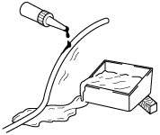
Oil Leakage Inspection
• Use either of the following procedures to identify the type of oil that is leaking:
Using UV light (black light)
1. Remove any oil on the engine or transaxle.
-
Note
-
• Referring to the fluorescent dye instruction manual, mix the specified amount of dye into the engine oil or ATF (or transaxle oil).
2. Pour the fluorescent dye into the engine oil or ATF (or transaxle oil).
3. Allow the engine to run for 30 min.
4. Inspect for dye leakage by irradiating with UV light (black light), and identify the type of oil that is leaking.
5. If no dye leakage is found, allow the engine to run for another 30 min. or drive the vehicle then reinspect.
6. Find where the oil is leaking from, then make necessary repairs.
-
Note
-
• To determine whether it is necessary to replace the oil after adding the fluorescent dye, refer to the fluorescent dye instruction manual.
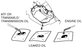
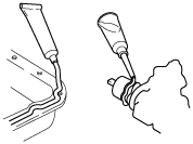
Not using UV light (black light)
1. Gather some of the leaking oil using an absorbent white tissue.
2. Take samples of engine oil and ATF (or transaxle oil), both from the dipstick, and place them next to the leaked oil already gathered on the tissue.
3. Compare the appearance and smell, and identify the type of oil that is leaking.
4. Remove any oil on the engine or transaxle/transmission.
5. Allow the engine to run for 30 min.
6. Check the area where the oil is leaking, then make necessary repairs.
Removal of Parts
• While correcting a problem, also try to determine its cause. Begin work only after first learning which parts and subassemblies must be removed and disassembled for replacement or repair. After removing the part, plug all holes and ports to prevent foreign material from entering.
Disassembly
• If the disassembly procedure is complex, requiring many parts to be disassembled, all parts should be marked in a place that will not affect their performance or external appearance and identified so that reassembly can be performed easily and efficiently.
Inspection During Removal, Disassembly
• When removed, each part should be carefully inspected for malfunction, deformation, damage and other problems.
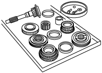
Arrangement of Parts
• All disassembled parts should be carefully arranged for reassembly.
• Be sure to separate or otherwise identify the parts to be replaced from those that will be reused.
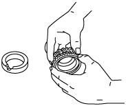
Cleaning of Parts
• All parts to be reused should be carefully and thoroughly cleaned in the appropriate method.
-
Warning
-
• Using compressed air can cause dirt and other particles to fly out causing injury to the eyes. Wear protective eye wear whenever using compressed air.
Reassembly
• Standard values, such as torques and certain adjustments, must be strictly observed in the reassembly of all parts.
• If removed, the following parts should be replaced with new ones:
-
― Oil seals
― Gaskets
― O-rings
― Lock washers
― Cotter pins
― Nylon nuts
• Depending on location:
-
― Sealant and gaskets, or both, should be applied to specified locations. When sealant is applied, parts should be installed before sealant hardens to prevent leakage.
― Oil should be applied to the moving components of parts.
― Specified oil or grease should be applied at the prescribed locations (such as oil seals) before reassembly.
Adjustment
• Use suitable gauges and testers when making adjustments.
Rubber Parts and Tubing
• Prevent gasoline or oil from getting on rubber parts or tubing.
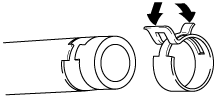
Hose Clamps
• When reinstalling, position the hose clamp in the original location on the hose and squeeze the clamp lightly with large pliers to ensure a good fit.
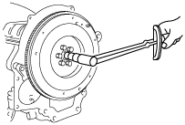
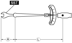
Torque Formulas
• When using a torque wrench-
SST or equivalent combination, the written torque must be recalculated due to the extra length that the
SST or equivalent adds to the torque wrench. Recalculate the torque by using the following formulas. Choose the formula that applies to you.
|
Torque Unit
|
Formula
|
|
N·m
|
N·m ×[L/(L+A)]
|
|
kgf·m
|
kgf·m ×[L/(L+A)]
|
|
kgf·cm
|
kgf·cm ×[L/(L+A)]
|
|
ft·lbf
|
ft·lbf ×[L/(L+A)]
|
|
in·lbf
|
in·lbf ×[L/(L+A)]
|
A :The length of the SST past the torque wrench drive.
L :The length of the torque wrench.
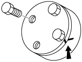
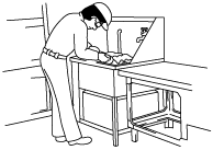
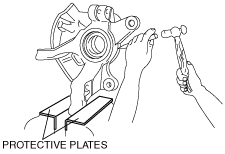
Vise
• When using a vise, put protective plates in the jaws of the vise to prevent damage to parts.
Dynamometer
• When inspecting and servicing the power train on the dynamometer or speed meter tester, pay attention to the following:
-
― Place a fan, preferably a vehicle-speed proportional type, in front of the vehicle.
― Make sure the vehicle is in a facility with an exhaust gas ventilation system.
― Since the rear bumper might deform from the heat, cool the rear with a fan. (Surface of the bumper must be 70 degrees or less.)
― Keep the area around the vehicle uncluttered so that heat does not build up.
― Watch the water temperature gauge and don’t overheat the engine.
― Avoid added load to the engine and maintain normal driving conditions as much as possible.
-
Note
-
• When only the front wheels are being rotated on the dynamometer, the ABS warning light could illuminate. If the ABS warning light illuminates, turn the ignition switch to the LOCK position, then turn it back to the ON position, run the vehicle at
10km/h and check that the ABS warning light goes off. (In this case, a DTC will be stored in the memory. To delete this data from the memory, follow the procedure for deleting DTCs (ABS) from memory.) (See
GENERAL PROCEDURES (BRAKE).) to turn off the warning light.)
SST
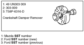
• Some global SST or equivalent are used as SSTs necessary for engine repair. Note that these SSTs are marked with global SST numbers.
• SST numbers are indicated in two ways, as shown in the following examples.
-
― 01–60 section: Both MAZDA and global SST numbers are indicated for reference.
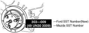
― Except 01–60 section: Either only the MAZDA SST number or both the MAZDA SST and global SST numbers are shown.
Example (60 section)
Example (except 60 section)