Diagnostic procedure
|
STEP
|
INSPECTION
|
ACTION
|
|
|---|---|---|---|
|
1
|
PERFORM DTC CONFIRMATION PROCEDURE
• Perform the DTC CONFIRMATION PROCEDURE.
(See DTC CONFIRMATION PROCEDURE.)
• Is the same DTC present?
|
Yes
|
Go to the next step.
|
|
No
|
Intermittent concern exists. Go to the INTERMITTENT CONCERN TROUBLESHOOTING procedure.
|
||
|
2
|
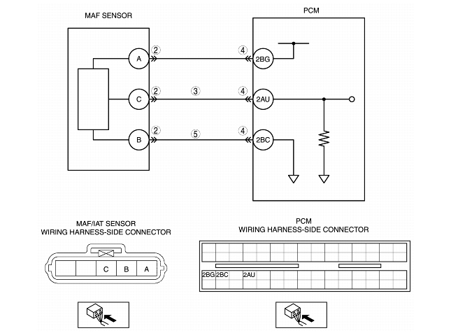
INSPECT MAF FOR POOR CONNECTION
• Turn the ignition switch off.
• Disconnect the MAF/IAT sensor connector.
• Inspect for poor connection (such as damaged, pulled-out pins, and corrosion).
• Is there any malfunction?
|
Yes
|
Repair or replace the terminals, then go to Step 6.
|
|
No
|
Go to the next step.
|
||
|
3
|
INSPECT MAF SIGNAL CIRCUIT FOR SHORT TO POWER CIRCUIT
• Turn the ignition switch to the ON position (Engine off).
• Measure the voltage between MAF/IAT sensor terminal C (wiring harness-side) and body ground.
• Is the voltage 0.1 V or less?
|
Yes
|
Go to the next step.
|
|
No
|
Repair or replace the suspected wiring harness, then go to Step 6.
|
||
|
4
|
INSPECT PCM FOR POOR CONNECTION
• Turn the ignition switch off.
• Disconnect the PCM connector.
• Inspect for poor connection (such as damaged, pulled-out pins, and corrosion).
• Is there any malfunction?
|
Yes
|
Repair the terminal, then go to Step 6.
|
|
No
|
Go to the next step.
|
||
|
5
|
INSPECT MAF SENSOR GROUND CIRCUIT FOR OPEN CIRCUIT
• Remove the PCM with the PCM connector connected.
• Inspect for continuity between MAF/IAT sensor terminal B (wiring harness-side) and ground.
• Is there continuity?
|
Yes
|
Replace the MAF/IAT sensor, then go to the next step.
|
|
No
|
Repair or replace the suspected wiring harness, then go to the next step.
|
||
|
6
|
VERIFY TROUBLESHOOTING OF DTC P0103 COMPLETED
• Make sure to reconnect all disconnected connectors.
• Clear the DTC from memory using the WDS or equivalent.
• Perform the KOEO/KOER self-test.
(See KOEO/KOER SELF-TEST.)
• Is same DTC present?
|
Yes
|
Replace the PCM, then go to the next step.
(See PCM REMOVAL/INSTALLATION.)
|
|
No
|
Go to the next step.
|
||
|
7
|
VERIFY AFTER REPAIR PROCEDURE
• Perform the "AFTER REPAIR PROCEDURE".
(See AFTER REPAIR PROCEDURE.)
• Are any DTCs present?
|
Yes
|
Go to applicable DTC troubleshooting.
(See DTC TABLE.)
|
|
No
|
Troubleshooting completed.
|
||