Diagnostic procedure
|
STEP
|
INSPECTION
|
ACTION
|
|
|---|---|---|---|
|
1
|
PERFORM DTC CONFIRMATION PROCEDURE
• Perform the DTC CONFIRMATION PROCEDURE.
(See DTC CONFIRMATION PROCEDURE.)
• Is the same DTC present?
|
Yes
|
Go to the next step.
|
|
No
|
Intermittent concern exists. Go to the INTERMITTENT CONCERN TROUBLESHOOTING procedure.
|
||
|
2
|
VERIFY RELATED PENDING AND STORED DTCS
• Turn the ignition switch off, then to the ON position (Engine off).
• Verify pending and stored DTCs using the WDS or equivalent.
• Are any other DTCs present?
|
Yes
|
Go to the applicable DTC troubleshooting procedures.
|
|
No
|
Go to the next step.
|
||
|
3
|
IDENTIFY TRIGGER DTC FOR FREEZE FRAME DATA
• Is DTC P0134 on the FREEZE FRAME DATA?
|
Yes
|
Go to the next step.
|
|
No
|
Go to the troubleshooting procedures for the DTC on the FREEZE FRAME DATA.
(See DTC TABLE.)
|
||
|
4
|
VERIFY CURRENT INPUT SIGNAL STATUS
• Warm up the engine.
• Access the O2S11 PID using the WDS or equivalent.
• Verify the PID while racing the engine (in NEUTRAL (MTX) or PARK (ATX)).
• Is the PID reading normal?
- More than 0.55 V when suddenly depressing the accelerator pedal (rich condition). - Less than 0.55 V just after releasing of the accelerator pedal (lean condition) |
Yes
|
Go to step 7.
|
|
No
|
Go to the next step.
|
||
|
5
|
INSPECT INSTALLATION OF HO2S
• Check if the HO2S is loosely installed.
• Is the sensor installed securely?
|
Yes
|
Go to the next step.
|
|
No
|
Install the sensor securely, then go to Step 9.
|
||
|
6
|
INSPECT GAS LEAKAGE FROM EXHAUST SYSTEM
• Visually check if any gas leakage is found between the exhaust manifold and the HO2S.
• Is there any gas leakage?
|
Yes
|
Repair or replace any the malfunctioning exhaust parts, then go to Step 9.
|
|
No
|
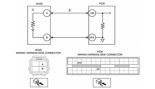
• Inspect the following wiring harnesses for an open or short circuit to ground circuit, repair or replace the wiring harness if necessary
• If all items above are normal, replace the malfunctioning sensor.
Then go to Step 9.
|
||
|
7
|
INSPECT SEALING OF ENGINE COOLANT PASSAGE
• Remove the radiator cap.
• Implement the procedure to bleed air from the engine coolant, then idle engine.
• Are there any small bubbles, that makes the engine coolant white at the filling opening?
|
Yes
|
Air gets in from poor sealing on the head gasket or other areas between the combustion chamber and engine coolant passage.
Repair or replace the malfunctioning parts, then go to Step 9.
|
|
No
|
Go to the next step.
|
||
|
8
|
INSPECT ENGINE COMPRESSION
• Inspect the engine compression.
• Is it normal?
|
Yes
|
Go to the next step.
|
|
No
|
Implement the engine overhaul for repairs, then go to the next step.
|
||
|
9
|
VERIFY TROUBLESHOOTING OF DTC P0134 COMPLETED
• Make sure to reconnect all disconnected connectors.
• Turn the ignition switch to the ON position (Engine off).
• Clear the DTC from memory using the WDS or equivalent.
• Perform the KOER self-test.
(See KOEO/KOER SELF-TEST.)
• Is the same DTC present?
|
Yes
|
Replace the PCM, then go to the next step.
(See PCM REMOVAL/INSTALLATION.)
|
|
No
|
Go to the next step.
|
||
|
10
|
VERIFY AFTER REPAIR PROCEDURE
• Perform the "AFTER REPAIR PROCEDURE".
(See AFTER REPAIR PROCEDURE.)
• Are any DTCs present?
|
Yes
|
Go to the applicable DTC troubleshooting.
(See DTC TABLE.)
|
|
No
|
Troubleshooting completed.
|
||