 |
am2zzw00004422
VALVE CLEARANCE ADJUSTMENT [ZJ, ZY]
id0110005036b7
1. Disconnect the negative battery cable.
2. Remove the front tire (RH).
3. Remove the ignition coil. (See IGNITION COIL REMOVAL/INSTALLATION [ZJ, ZY].)
4. Remove the ventilation hose.
5. Remove the cylinder head cover.
6. Remove the drive belt. (See DRIVE BELT REPLACEMENT [ZJ, ZY].)
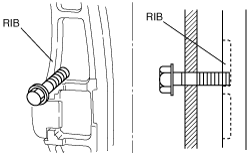
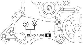
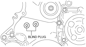
7. Remove the engine front cover blind plug as shown in the figure.
am2zzw00004422
|
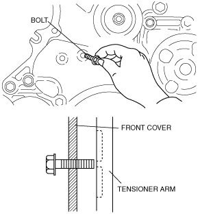
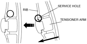
8. Insert a M10 or M6 bolt (45—80 mm {1.8—3.1 in} length bolt with threads to the end) into the service hole (right side) by hand as shown in the figure. Pull back the inserted bolt approx. 2 mm {0.08 in} from where it contacts the tensioner arm (loosen the M10 bolt approx. two turns), and set the bolt in a position slightly outward of the tensioner arm.
|
Insert Bolt |
Front Cover Service Hole |
|---|---|
|
M10 × 1.25
|
10 mm {0.39 in}
|
|
M6 × 1.25
|
7 mm {0..3 in}
|
am2zzw00004249
|
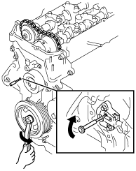
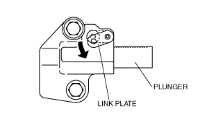
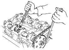
9. Release tension on the timing chain.
am2zzw00004250
|
am2zzw00004251
|
am2zzw00004252
|
am2zzw00004253
|
10. Fix the camshaft using a wrench on the cast hexagon. Remove the camshaft sprocket installation bolt.
am2zzw00004254
|
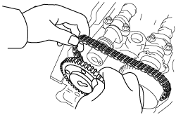
11. Remove the timing sprocket on the exhaust side with the timing chain positioned out of the way.
am2zzw00004255
|
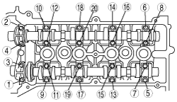
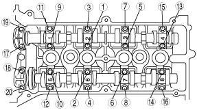
12. Loosen the camshaft cap installation bolts in two or three steps in the order shown in the figure, and remove the camshaft caps.
am2zzw00004256
|
13. Remove the intake and exhaust camshafts.
14. Remove the tappet.
15. Select a proper tappet according to the result of the valve clearance inspection and install it.
Tappet to be selected: thickness of the removed tappet + measured valve clearance – standard valve clearance (IN: 0.3 mm {0.0118 in}, EX: 0.3 mm {0.0118 in})
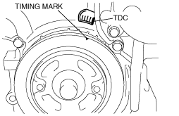
16. Align the timing marks on the crank pulley and the front cover, and then align the No.1 cylinder to the TDC.
am2zzw00004257
|
17. Install the intake and exhaust camshafts with the No.1 cylinder so that it is near TDC of the compression stroke.
18. Install the camshaft caps to the position shown in the figure, and temporarily tighten the No.2 and No.7 camshaft installation bolts.
19. Tighten the camshaft installation bolts in two or three steps uniformly in the order shown in the figure.
am2zzw00004258
|
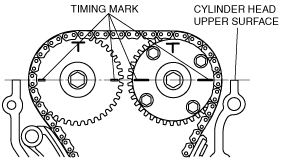
20. Align the sprocket timing marks on the intake and exhaust camshafts so that they form a straight line in alignment with the upper horizontal surface of the cylinder head.
am2zzw00004259
|
21. Fix the camshaft using a wrench on the cast hexagon. Install the camshaft sprocket installation bolt.
22. Remove the M10 or M6 bolt holding the tensioner arm.
23. Verify that there is no slack in the timing chain, and then verify that the marks on the camshaft sprocket and the crank pulley are aligned.
24. Inspect the valve timing by rotating the crankshaft clockwise twice.
25. Install the engine front cover blind plug with a new washer. (Service Hole : 10 mm {0.39 in})
am2zzw00004422
|
26. Install the new engine front cover blind plug. (Service Hole : 7 mm {0.3 in})
am3zzw00006290
|
27. Install the drive belt. (See DRIVE BELT REPLACEMENT [ZJ, ZY].)
28. Install the cylinder head cover. (See TIMING CHAIN REMOVAL/INSTALLATION [ZJ, ZY].)
29. Install the ventilation hose.
30. Install the ignition coils. (See IGNITION COIL REMOVAL/INSTALLATION [ZJ, ZY].)
31. Install the front tire (RH).