FUEL HOSE (ENGINE ROOM SIDE) REMOVAL/INSTALLATION
id011400810100
-
Warning
-
• Fuel line spills and leakage are dangerous. Fuel can ignite and cause serious injuries or death and damage. Fuel can also irritate skin and eyes. To prevent this, always complete the "Fuel Line Safety Procedure".
Removal
-
Caution
-
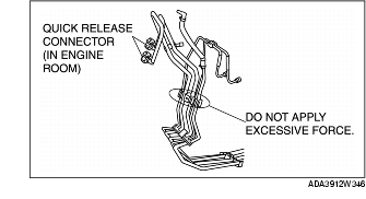
• Applying excessive force to the pressed in areas of the fuel hoses could damage the fuel pipes resulting in fuel leakage. When removing the fuel hoses, temporarily support them against something so that no excessive force is applied to the pressed areas of the fuel hoses.
1. Complete the "BEFORE REPAIR PROCEDURE". (See BEFORE REPAIR PROCEDURE.)
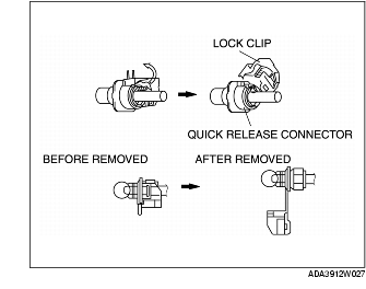
2. Remove the lock clip.
-
Caution
-
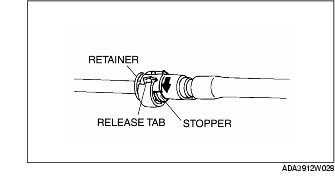
• The quick release connector may be damaged if the release tab is bent excessively. Do not expand the release tab over the stopper.
-
Note
-
• The fuel hose may be removed easily by rotating the release tab while the fuel hose is slightly pressed to fuel pipe side.
3. Rotate the quick release connector release tab to the stopper position.
-
Note
-
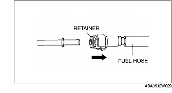
• After disconnecting the fuel hose, the retainer may be removed from the quick release connector. Take care not to lose the retainer.
4. Pull out the fuel hose straight from the fuel pipe and remove it.
-
Note
-
• Take care to prevent damage or soiling of the fuel hose.
5. Cover the disconnected quick release connector and fuel pipe with vinyl sheeting or a similar material to prevent it from being scratched or contaminated with foreign material.
Installation
-
Caution
-
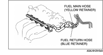
• Install the fuel main hose to the yellow-marked pipe, and the fuel return hose to the blue-marked pipe.
-
Note
-
• If the quick release connector O-ring is damaged or has slipped, replace the plastic fuel hose.
1. Inspect the fuel hose and fuel pipe sealing surface for damage and deformation.
-
• If there is any malfunction, replace the concerned part.
2. Apply a small amount of clean engine oil to the sealing surface of the fuel pipe.
3. Reconnect the fuel hose straight to the fuel pipe until a click is heard.
-
Note
-
• If the quick release connector does not move at all, disconnect it and verify that the O-ring is not damaged or has slipped, then reconnect the quick release connector.
4. Lightly pull and push the quick release connector a few times by hand and verify that it can move 2.0-3.0 mm {0.08-0.11 in} and it is connected securely.
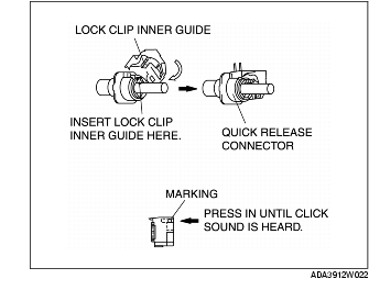
5. Install the lock clip using the following procedure.
-
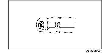
(1) Insert the inner guide as shown in the figure.
-
(2) Push the lock clip from the back of the marking until a click is heard to lock it.
6. Complete the "AFTER REPAIR PROCEDURE". (See AFTER REPAIR PROCEDURE.)