 |
am2zzw00004570
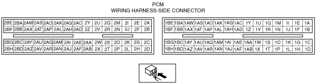
PCM INSPECTION [WITHOUT WU-TWC]
id0140008025d3
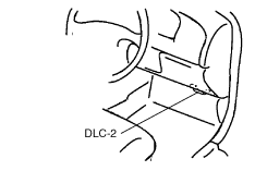
1. Connect the WDS or equivalent to the DLC-2.
am2zzw00004570
|
2. Turn the ignition switch to the ON position.
3. Inspect the monitor items.
PID/DATA monitor table (reference)
|
Monitor item (definition) |
Unit/Condition |
Condition/Specification (Reference) |
Inspection item(s) |
PCM terminal |
|---|---|---|---|---|
|
A/CL V
(Refrigerant pressure switch (Low, high))
|
V
|
• A/C is not operating: Approx. 5 V
• A/C is operating: 1.0 V or less
|
• Refrigerant pressure switch (Low, high)
|
1Q
|
|
A/CT
(Evaporator temperature)
|
°C, °F
|
• Evaporator temperature is 20°C {68°F}: 20°C {68°F}
|
• Evaporator temperature sensor
|
1AD
|
|
A/CT V
(Evaporator temperature (Voltage))
|
V
|
• Evaporator temperature is 20°C {68°F}: 2.5 V
|
• Evaporator temperature sensor
|
1AD
|
|
ACCS
(A/C relay)
|
On/Off
|
• A/C is operating: On
• A/C is not operating: Off
|
• Inspect the following monitor items:
|
1AL
|
|
ACSW
(A/C switch)
|
On/Off
|
• A/C switch is on: On
• A/C switch is off: Off
|
• A/C switch
|
1Q
|
|
ALTF
(Generator field coil control duty value)
|
%
|
• Ignition switch is ON: 0%
• Idling, E/L is operating: Duty value increases.
|
• Inspect the following monitor items:
• Generator
|
2AN
|
|
ALTT V
(Generator output voltage)
|
V
|
• Ignition switch is ON: Approx. 1.0 V or less
• Idling (No electrical load): Approx. 14.9 V (This is an internal calculation value and differs from the terminal voltage.)
|
• Inspect the following monitor items:
• Generator
|
2AR
|
|
ARPMDES
(Target engine speed)
|
RPM
|
• No load: 700 RPM
• A/C is operating (A/C pressure switch (Middle) is on): 750 RPM
• E/L is operating: 750 RPM
• P/S is operating: 750 RPM
|
• Inspect the following monitor items:
• IAC valve
|
—
|
|
BOO
(Brake switch)
|
On/Off
|
• Brake pedal is depressed: On
• Brake pedal is released: Off
|
• Brake switch
|
1V
|
|
CPP*1
(Clutch pedal position)
|
On/Off
|
• Clutch pedal is depressed: On
• Clutch pedal is released: Off
|
• Clutch switch
|
1P
|
|
CPP/PNP*1
(Shift lever position)
|
Drive/Neutral
|
• Neutral: Neutral
• Other than neutral: Drive
|
• Neutral switch
|
1AB
|
|
DTCCNT
(Number of DTC detected)
|
—
|
• Number of DTCs output
|
—
|
—
|
|
ECT
(Engine coolant temperature)
|
°C, °F
|
• ECT is 20°C {68°F}: 20°C {68°F}
• ECT is 60°C {140°F}: 60°C {140°F}
• ECT is 80°C {176°F}: 80°C {176°F}
|
• ECT sensor
|
2J
|
|
V
|
• ECT is 20°C {68°F}: Approx. 3.0 V
• ECT is 60°C {140°F}: Approx. 1.4 V
• ECT is 80°C {176°F}: Approx. 0.9 V
|
|||
|
EVAPCP
(Purge solenoid valve duty value)
|
%
|
• Ignition switch is ON: 0%
• Idling: 10%
|
• Inspect the following monitor items:
|
2AV
|
|
FAN1
(Fan relay No.1 control)
|
On/Off
|
• During test mode
CTP: Off
WOT: On
|
• Inspect the following monitor items:
|
1AT
|
|
FAN2
(Fan relay No.2 control)
|
On/Off
|
• During test mode
CTP: Off
WOT: On
|
• Inspect the following monitor items:
|
1I
|
|
FP
(Fuel pump relay)
|
On/Off
|
• Ignition switch is ON: Off
• Idling or cranking: On
|
• Fuel pump relay
|
*41AC
|
|
*51AH
|
||||
|
FUELPW
(Fuel injector duration)
|
ms
|
• Idling: Approx. 3.0 ms
|
• Inspect the following monitor items:
|
2B, 2C, 2D, 2H
|
|
FUELSYS
(Fuel system status)
|
OL_Drive/
OL/
CL_Fault/
OL_Fault/
CL
|
• Idling after completely warmed up: CL
• Deceleration with CTP: OL
|
• Inspect the following monitor items:
|
—
|
|
GEAR*2
|
||||
|
GENVDSD
(Generator voltage desired)
|
V
|
• Idling (no electrical load): Approx. 14.9 V (This is an internal calculation value and differs from the terminal voltage.)
|
• Inspect the following monitor items:
• Generator
|
—
|
|
HTR11
(HO2S heater control)
|
On/Off
|
• Ignition switch is ON: Off
• Engine speed is 4,300 rpm or less: On
|
• Inspect the following monitor items:
|
2AM
|
|
IAC
(IAC valve control)
|
%
|
• Ignition switch is ON: 0%
• Idling (ECT is 90°C {194°F}, no load condition): Approx. 23%
|
• Inspect the following monitor items:
|
2X, 2AB
|
|
IAT
(Intake air temperature)
|
V
|
• IAT is 20°C {68°F}: Approx. 2.5 V
• IAT is 30°C {86°F}: Approx. 1.8 V
|
• IAT sensor
|
2AQ
|
|
°C, °F
|
• IAT is 20°C {68°F}: 20°C {68°F}
• IAT is 30°C {86°F}: 30°C {86°F}
|
|||
|
IMRC
(VTCS)
|
On/Off
|
• Cold start and 3,250 rpm or less: On
• Hot start or 3,250 rpm or more: Off
|
• Inspect the following monitor items:
|
2AF, 2AJ
|
|
IMTV*3
(VIS)
|
On/Off
|
• Engine speed is less than 4,100 rpm: On
• Engine speed is 4,100 rpm or more: Off
|
• Inspect the following monitor items:
|
2AO, 2AS
|
|
INGEAR
(Gears are engaged.)
|
On/Off
|
• Clutch pedal is released: On
• Clutch pedal is depressed: Off
• Other than neutral: On
• Neutral: Off
|
• Clutch switch
• Neutral switch
|
*11P, 1AB
|
|
• Other than P and N positions: On
• P or N position: Off
|
• TR switch
|
*2—
|
||
|
IVS
(CTP condition)
|
Idle/Off Idle
|
• Idling: Idle
• Other than idling: Off Idle
|
• Inspect the following monitor item:
|
2AA
|
|
KNOCKR
(Knocking retard)
|
°
|
• Ignition switch is at the ON position: 0°
• Idling: 0°
|
• Knock sensor
|
2BA
|
|
LINEDES*2
|
||||
|
LOAD
(Engine load (charging efficiency))
|
%
|
• Idling (After warm-up): Approx. 19%
|
• DTC inspection
|
—
|
|
LONGFT1
(Long term fuel trim)
|
%
|
• Idling (After warm-up): Approx. –14—+14%
|
• DTC inspection
|
—
|
|
LPS*2
|
||||
|
MAF
(Mass air flow)
|
g/s
|
• Ignition switch is ON: Approx. 0 g/s
• Idling: Approx. 2.7 g/s
|
• MAF sensor
|
2AU
|
|
V
|
• Ignition switch is ON: Approx. 0.7 V
• Idling: Approx. 1.3 V
|
|||
|
MIL
(Malfunction indicator lamp)
|
On/Off
|
• Ignition switch is ON: On
• Idling: Off
|
• DTC inspection
|
—
|
|
MIL_DIS
(Distance travelled since MIL illuminated)
|
km, mile
|
• Distance travelled MIL illuminated
|
—
|
—
|
|
O2S11
(HO2S voltage)
|
V
|
• Ignition switch is ON: 1.0 V or less
• Idling (After warm-up): Alternates between 0 and 1.0 V
• Acceleration (After warm-up):
Alternates between 0.5 and 1.0 V
• Deceleration (After warm-up):
Alternates between 0 and 0.5 V
|
• HO2S
|
2AI
|
|
Rich/Lean
|
• Acceleration (After warm-up):
Rich
• Deceleration (After warm-up):
Lean
|
|||
|
PSP
(PSP switch)
|
High/Low
|
• Steering wheel is in straight ahead position: Low
• Steering wheel is fully turned: High
|
• PSP switch
|
2AC
|
|
RFCFLAG
(Readiness function code)
|
Learnt/Not Learnt
|
• Idling (After running PCM adaptive memory procedure drive mode): Learnt
• Right after the negative battery cable is disconnected (Before running PCM adaptive memory procedure drive mode): Not Learnt
|
• Perform “AFTER REPAIR PROCEDURE”.
|
—
|
|
RPM
(Engine speed)
|
RPM
|
• Idling (No load): 650—750 RPM
|
• CKP sensor
|
2P
|
|
SHRTFT1
(Short term fuel trim)
|
%
|
• Idling (After warm-up): –3—+25%
|
• DTC inspection
|
—
|
|
SPARKADV
(Ignition timing)
|
° (BTDC)
|
• During test mode: BTDC 9—11° (BTDC)
• Idling: BTDC 6—18° (BTDC)
|
• Inspect the following monitor items:
|
2BB
|
|
SSA/SS1*2
|
||||
|
SSB/SS2*2
|
||||
|
SSC/SS3*2
|
||||
|
TCS*2
|
||||
|
test
(Test mode)
|
On/Off
|
• During test mode: On
• Other than test mode: Off
|
—
|
—
|
|
TFT*2
|
||||
|
TFTV*2
|
||||
|
THOP*2
|
||||
|
TP
(TP)
|
%
|
• CTP: 0%
• WOT:100%
|
• TP sensor
|
2AA
|
|
V
|
• CTP: 0.3—1.0 V
• WOT: 3.1—4.5 V
|
|||
|
TP REL
(Throttle position signal (relative value))
|
%
|
• CTP: 0%
• WOT: 100%
|
• TP sensor
|
2AA
|
|
TPCT
(TP sensor voltage at CTP)
|
V
|
• 0.3—1.0 V
|
• TP sensor
|
2AA
|
|
TR*2
|
||||
|
TR_SENS*2
|
||||
|
TSS*2
|
||||
|
VPWR
(Battery positive voltage)
|
V
|
• Ignition switch is ON: B+
• Idling: B+
|
• Battery
• Main relay
|
1AX, 1BF, 1BG
|
|
VSS
(Vehicle speed)
|
KPH, MPH
|
• Vehicle is stopped: 0 KPH {0 MPH}
• Vehicle speed is 25 km/h: 25 KPH {16 MPH}
|
• VSS
|
*11AA, 1AE
|
|
*21AY, 1BC
|
||||
|
VT DUTY1
(OCV control)
|
%
|
• Idling: Approx. 10%
|
• Inspect the following monitor items:
|
2AK, 2AG
|
Without Using WDS or Equivalent
am2zzw00004571
|
Terminal voltage table (Reference)
|
Terminal |
Signal |
Connected to |
Test condition |
Voltage (V) |
Inspection item(s) |
|
|---|---|---|---|---|---|---|
|
1A
|
—
|
—
|
—
|
—
|
—
|
|
|
1B
|
—
|
—
|
—
|
—
|
—
|
|
|
1C
|
—
|
—
|
—
|
—
|
—
|
|
|
1D
|
—
|
—
|
—
|
—
|
—
|
|
|
1E
|
—
|
—
|
—
|
—
|
—
|
|
|
1F
|
—
|
—
|
—
|
—
|
—
|
|
|
1G*1
|
GND
|
Input/turbine speed sensor shield wire
|
Under any condition
|
1.0 or less
|
• Related harness
|
|
|
1H
|
—
|
—
|
—
|
—
|
—
|
|
|
1I
|
Electric fan control
|
Cooling fan relay No. 2
|
Test mode is on*2
|
CTP
|
B+
|
• Cooling fan relay No.2
• Related harness
|
|
WOT
|
1.0 or less
|
|||||
|
1J
|
—
|
—
|
—
|
—
|
—
|
|
|
1K*1
|
Input/turbine speed sensor (–)
|
Input/turbine speed sensor
|
Inspect using the wave profile.
|
• Input/turbine speed sensor
• Related harness
|
||
|
1L
|
—
|
—
|
—
|
—
|
—
|
|
|
1M
|
—
|
—
|
—
|
—
|
—
|
|
|
1N
|
GND
|
Evaporator temperature sensor
|
Under any condition
|
1.0 or less
|
• Related harness
|
|
|
1O*1
|
Input/turbine speed sensor (+)
|
Input/turbine speed sensor
|
Inspect using the wave profile.
|
• Input/turbine speed sensor
• Related harness
|
||
|
1P*3
|
Clutch switch
|
Clutch switch
|
Ignition switch is ON
|
Clutch pedal depressed
|
1.0 or less
|
• Clutch switch
• Related harness
|
|
Clutch pedal released
|
Approx. 6.3
|
|||||
|
1Q
|
A/C operation
|
A/C switch, refrigerant pressure switch (Low, high)
|
Ignition switch is ON
|
A/C switch is off
|
Approx. 5.0
|
• A/C switch
• Refrigerant pressure switch (Low, high)
• Related harness
|
|
A/C switch and fan switch are on
|
1.0 or less
|
|||||
|
1R
|
—
|
—
|
—
|
—
|
—
|
|
|
1S
|
CAN_L
|
Instrument cluster, ABS HU/CM, DLC-2
|
Because this terminal is for CAN, good/no good determination of terminal voltage is not possible.
|
—
|
||
|
1T
|
—
|
—
|
—
|
—
|
—
|
|
|
1U
|
Refrigerant pressure (Middle)
|
Refrigerant pressure switch (Middle)
|
Idle
|
Refrigerant pressure is 1.52 MPa {15.5 kgf/cm2, 221 psi} or more
|
1.0 or less
|
• Refrigerant pressure switch (Middle)
• Related harness
|
|
Refrigerant pressure is 12.3 MPa {125 kgf/cm2, 1783 psi} or less
|
B+
|
|||||
|
1V
|
Brake switch
|
Brake switch
|
Brake pedal depressed
|
B+
|
• Brake switch
• Related harness
|
|
|
Brake pedal released
|
1.0 or less
|
|||||
|
1W
|
CAN_H
|
Instrument cluster, ABS HU/CM, DLC-2
|
Because this terminal is for CAN, good/no good determination of terminal voltage is not possible.
|
—
|
||
|
1X*1
|
Selector lever position
|
TR switch
|
Ignition switch is ON
|
P position
|
Approx. 4.6
|
• TR switch
• Related harness
|
|
R position
|
Approx. 3.9
|
|||||
|
N position
|
Approx. 3.2
|
|||||
|
D range
|
Approx. 2.5
|
|||||
|
S range
|
Approx. 1.7
|
|||||
|
L range
|
Approx. 0.94
|
|||||
|
1Y
|
—
|
—
|
—
|
—
|
—
|
|
|
1Z
|
Vehicle speed output
|
Car-navigation unit
|
Inspect using the wave profile.
|
• Car-navigation unit
• Related harness
|
||
|
1AA*3
|
Vehicle speed (–)
|
VSS
|
Under any condition
|
1.0 or less
|
• VSS
• Related harness
|
|
|
1AB*3
|
Neutral switch
|
Neutral switch
|
Ignition switch is ON
|
Neutral
|
1.0 or less
|
• Neutral switch
• Related harness
|
|
Except above
|
Approx. 6.3
|
|||||
|
1AC*6
|
Fuel pump control
|
Fuel pump relay
|
Ignition switch is ON
|
B+
|
• Fuel pump relay
• Related harness
|
|
|
Cranking
|
1.0 or less
|
|||||
|
Idle
|
||||||
|
1AD
|
Evaporator temperature
|
Evaporator temperature sensor
|
Ignition switch is ON
|
Evaporator temperature is 20 °C {68 °F}
|
Approx. 2.5
|
• Evaporator temperature sensor
• Related harness
|
|
1AE*3
|
Vehicle speed (+)
|
VSS
|
Inspect using the wave profile.
|
• VSS
• Related harness
|
||
|
1AF*1
|
Pressure control solenoid (+)
|
Pressure control solenoid
|
Idle
|
B+
|
• Pressure control solenoid
• Related harness
|
|
|
1AG*6
|
Security light control
|
Instrument cluster (security light)
|
Security light illuminates
|
1.0 or less
|
• Instrument cluster
• Related harness
|
|
|
Security light does not illuminate
|
B+
|
|||||
|
1AH*7
|
Fuel pump control
|
Fuel pump relay
|
Ignition switch is ON
|
B+
|
• Fuel pump relay
• Related harness
|
|
|
Cranking
|
1.0 or less
|
|||||
|
Idle
|
||||||
|
1AI
|
—
|
—
|
—
|
—
|
—
|
|
|
1AJ*1
|
Shift solenoid D
|
Shift solenoid D
|
P or N position
|
B+
|
• Shift solenoid D
• Related harness
|
|
|
Except above
|
1.0 or less
|
|||||
|
1AK*6
|
Starter relay control
|
Starter relay
|
Cranking
|
1.0 or less
|
• Starter relay
• Related harness
|
|
|
1AL
|
A/C cut-off control
|
A/C relay
|
A/C is operating
|
1.0 or less
|
• A/C relay
• Related harness
|
|
|
A/C is not operating
|
B+
|
|||||
|
1AN*1
|
GND
|
TFT sensor, TR switch
|
Under any condition
|
1.0 or less
|
• Related harness
|
|
|
1AO*6
|
Immobilizer system communication
|
Coil
|
Because this terminal is for communication, good/no good determination of terminal voltage is not possible.
|
—
|
||
|
1AP
|
—
|
—
|
—
|
—
|
—
|
|
|
1AQ*1
|
HOLD switch
|
HOLD switch
|
Ignition switch is ON
|
HOLD switch pushed
|
1.0 or less
|
• HOLD switch
• Related harness
|
|
HOLD switch released
|
B+
|
|||||
|
1AR*1
|
Shift solenoid E
|
Shift solenoid E
|
During TCC operation
|
B+
|
• Shift solenoid E
• Related harness
|
|
|
Except above
|
1.0 or less
|
|||||
|
1AS*6
|
Immobilizer system communication
|
Coil
|
Because this terminal is for communication, good/no good determination of terminal voltage is not possible.
|
—
|
||
|
1AT
|
Electric fan control
|
Cooling fan relay No. 1
|
Test mode is on*2
|
CTP
|
B+
|
• Cooling fan relay No.1
• Related harness
|
|
WOT
|
1.0 or less
|
|||||
|
1AU*1
|
ATF temperature
|
TFT sensor
|
Ignition switch is ON
|
TFT is 20 °C {68 °F}
|
Approx. 3.3
|
• TFT sensor
• Related harness
|
|
TFT is 40 °C {104 °F}
|
Approx. 2.4
|
|||||
|
TFT is 60 °C {140 °F}
|
Approx. 1.5
|
|||||
|
1AV*1
|
Pressure control solenoid (–)
|
Pressure control solenoid
|
Inspect using the wave profile.
|
• Pressure control solenoid
• Related harness
|
||
|
1AW
|
Main relay
|
Main relay
|
Ignition switch is off
|
1.0 or less
|
• Main relay
• Related harness
|
|
|
Ignition switch is ON
|
||||||
|
1AX
|
Back-up power supply
|
Battery
|
Under any condition
|
B+
|
• Battery
• Related harness
|
|
|
1AY*1
|
Vehicle speed
|
VSS
|
Inspect using the wave profile.
|
• VSS
• Related harness
|
||
|
1AZ*1
|
Shift solenoid A
|
Shift solenoid A
|
Inspect using the wave profile.
|
• Shift solenoid A
• Related harness
|
||
|
1BA
|
ECT output
|
Climate control unit
|
Ignition switch is ON
|
ECT is 20 °C {68 °F}
|
Approx. 3.0
|
• Climate control unit
• Related harness
|
|
ECT is 60 °C {140 °F}
|
Approx. 1.4
|
|||||
|
ECT is 80 °C {176 °F}
|
Approx. 0.9
|
|||||
|
1BB
|
Battery voltage
|
Main relay
|
Ignition switch is off
|
1.0 or less
|
• Main relay
• Battery
• Related harness
|
|
|
Ignition switch is ON
|
B+
|
|||||
|
1BC*1
|
VSS power supply
|
VSS
|
Ignition switch is ON
|
B+
|
• Related harness
|
|
|
1BD*1
|
Shift solenoid C
|
Shift solenoid C
|
Inspect using the wave profile.
|
• Shift solenoid C
• Related harness
|
||
|
1BE
|
Ignition switch
|
Ignition switch
|
Ignition switch is off
|
1.0 or less
|
• Ignition switch
• Related harness
|
|
|
Ignition switch is ON
|
B+
|
|||||
|
1BF
|
Battery voltage
|
Main relay
|
Ignition switch is off
|
1.0 or less
|
• Main relay
• Battery
• Related harness
|
|
|
Ignition switch is ON
|
B+
|
|||||
|
1BG*1
|
Battery voltage
|
Main relay
|
Ignition switch is off
|
1.0 or less
|
• Main relay
• Battery
• Related harness
|
|
|
Ignition switch is ON
|
B+
|
|||||
|
1BH*1
|
Shift solenoid B
|
Shift solenoid B
|
Inspect using the wave profile.
|
• Shift solenoid B
• Related harness
|
||
|
2A
|
Ignition coil power supply
|
Ignition coil
|
Ignition switch is ON
|
B+
|
• Related harness
|
|
|
2B
|
Fuel injection control
|
Fuel injector No.1
|
Inspect using the wave profile.
|
• Fuel injector No.1
• Related harness
|
||
|
2C
|
Fuel injection control
|
Fuel injector No.2
|
Inspect using the wave profile.
|
• Fuel injector No.2
• Related harness
|
||
|
2D
|
Fuel injection control
|
Fuel injector No.3
|
Inspect using the wave profile.
|
• Fuel injector No.3
• Related harness
|
||
|
2E
|
Fuel injector No.1 power supply
|
Fuel injector No.1
|
Ignition switch is ON
|
B+
|
• Related harness
|
|
|
2F
|
Fuel injector No.2 power supply
|
Fuel injector No.2
|
Ignition switch is ON
|
B+
|
• Related harness
|
|
|
2G
|
Fuel injector No.3 power supply
|
Fuel injector No.3
|
Ignition switch is ON
|
B+
|
• Related harness
|
|
|
2H
|
Fuel injection control
|
Fuel injector No.4
|
Inspect using the wave profile.
|
• Fuel injector No.4
• Related harness
|
||
|
2I
|
—
|
—
|
—
|
—
|
—
|
|
|
2J
|
ECT
|
ECT sensor
|
Ignition switch is ON
|
ECT is 20 °C {68 °F}
|
Approx. 3.0
|
• ECT sensor
• Related harness
|
|
ECT is 60 °C {140 °F}
|
Approx. 1.4
|
|||||
|
ECT is 80 °C {176 °F}
|
Approx. 0.9
|
|||||
|
2K
|
—
|
—
|
—
|
—
|
—
|
|
|
2L
|
Fuel injector No.4 power supply
|
Fuel injector No.4
|
Ignition switch is ON
|
B+
|
• Related harness
|
|
|
2M
|
ESA control
|
Ignition coil No.4
|
Inspect using the wave profile.
|
• Ignition coil No.4
• Related harness
|
||
|
2N
|
—
|
—
|
—
|
—
|
—
|
|
|
2O
|
—
|
—
|
—
|
—
|
—
|
|
|
2P
|
CKP
|
CKP sensor
|
Inspect using the wave profile.
|
• CKP sensor
• Related harness
|
||
|
2Q
|
ESA control
|
Ignition coil No.3
|
Inspect using the wave profile.
|
• Ignition coil No.3
• Related harness
|
||
|
2R
|
—
|
—
|
—
|
—
|
—
|
|
|
2S
|
—
|
—
|
—
|
—
|
—
|
|
|
2T
|
Input/output device power supply
|
CKP sensor, CMP sensor, HO2S, purge solenoid valve
|
Ignition switch is ON
|
B+
|
• Related harness
|
|
|
2U
|
ESA control
|
Ignition coil No.2
|
Inspect using the wave profile.
|
• Ignition coil No.2
• Related harness
|
||
|
2V
|
—
|
—
|
—
|
—
|
—
|
|
|
2W
|
Constant voltage (Vref)
|
TP sensor
|
Ignition switch is ON
|
Approx. 5.0
|
• TP sensor
• Related harness
|
|
|
2X
|
IAC (+)
|
IAC valve
|
Idle
|
B+
|
• IAC valve
• Related harness
|
|
|
2Y
|
ESA control
|
Ignition coil No.1
|
Inspect using the wave profile.
|
• Ignition coil No.1
• Related harness
|
||
|
2Z
|
—
|
—
|
—
|
—
|
—
|
|
|
2AA
|
TP
|
TP sensor
|
Ignition switch is ON
|
CTP
|
0.3—1.0
|
• TP sensor
• Related harness
|
|
WOT
|
3.1—4.5
|
|||||
|
2AB
|
IAC (–)
|
IAC valve
|
Inspect using the wave profile.
|
• IAC valve
• Related harness
|
||
|
2AC
|
PSP switch
|
PSP switch
|
Idle
|
Steering wheel at straight ahead position
|
B+
|
• PSP switch
• Related harness
|
|
While turning steering wheel
|
1.0 or less
|
|||||
|
2AD
|
—
|
—
|
—
|
—
|
—
|
|
|
2AE
|
GND
|
TP sensor
|
Under any condition
|
1.0 or less
|
• Related harness
|
|
|
2AF
|
VTCS (Open)
|
VTCS shutter valve actuator
|
Engine is hot
|
When ignition switch is ON.
|
B+*5
|
• VTCS shutter valve actuator
• Related harness
|
|
Idle after cold start
|
When the ECT reaches 60 °C {140 °F}
|
|||||
|
Except above
|
1.0 or less
|
|||||
|
2AG
|
Variable valve timing control (–)
|
OCV
|
Under any condition
|
1.0 or less
|
• OCV
• Related harness
|
|
|
2AH
|
—
|
—
|
—
|
—
|
—
|
|
|
2AI
|
Oxygen concentration
|
HO2S
|
Inspect using the wave profile.
|
• HO2S
• Related harness
|
||
|
2AJ
|
VTCS (Close)
|
VTCS shutter valve actuator
|
Engine is cold
|
When ignition switch is ON.
|
B+*5
|
• VTCS shutter valve actuator
• Related harness
|
|
Except above
|
1.0 or less
|
|||||
|
2AK
|
Variable valve timing control (+)
|
OCV
|
Inspect using the wave profile.
|
• OCV
• Related harness
|
||
|
2AL
|
—
|
—
|
—
|
—
|
—
|
|
|
2AM
|
HO2S heater control
|
HO2S heater
|
Inspect using the wave profile.
|
• HO2S heater
• Related harness
|
||
|
2AN
|
Generator control
|
Generator (Terminal D)
|
Inspect using the wave profile.
|
• Generator
• Related harness
|
||
|
2AO*4
|
VIS (Open)
|
VIS shutter valve actuator
|
When ignition switch is ON.
|
1.0 or less
|
• VIS shutter valve actuator
• Related harness
|
|
|
When the engine speed is increased gradually and reaches 4,100 rpm.
|
B+*5
|
|||||
|
Except above
|
1.0 or less
|
|||||
|
2AP
|
—
|
—
|
—
|
—
|
—
|
|
|
2AQ
|
IAT
|
IAT sensor
|
Ignition switch is ON
|
IAT is 20 °C {68 °F}
|
Approx. 2.5
|
• IAT sensor
• Related harness
|
|
IAT is 30 °C {86 °F}
|
Approx. 1.8
|
|||||
|
2AR
|
Generator output voltage
|
Generator (terminal P)
|
Inspect using the wave profile.
|
• Generator
• Related harness
|
||
|
2AS*4
|
VIS (Close)
|
VIS shutter valve actuator
|
When ignition switch is ON.
|
B+*5
|
• VIS shutter valve actuator
• Related harness
|
|
|
When the engine speed is decreased gradually and reaches 4,100 rpm.
|
||||||
|
Except above
|
1.0 or less
|
|||||
|
2AT
|
—
|
—
|
—
|
—
|
—
|
|
|
2AU
|
MAF
|
MAF sensor
|
Ignition switch is ON
|
Approx. 0.7
|
• MAF sensor
• Related harness
|
|
|
Idle
|
Approx. 1.3
|
|||||
|
2AV
|
Purge control
|
Purge solenoid valve
|
Inspect using the wave profile.
|
• Purge solenoid valve
• Related harness
|
||
|
2AW
|
—
|
—
|
—
|
—
|
—
|
|
|
2AX
|
GND
|
ECT sensor, HO2S
|
Under any condition
|
1.0 or less
|
• Related harness
|
|
|
2AY
|
GND
|
IAT sensor
|
Under any condition
|
1.0 or less
|
• Related harness
|
|
|
2AZ
|
GND
|
GND
|
Under any condition
|
1.0 or less
|
• Related harness
|
|
|
2BA
|
Knocking
|
Knock sensor
|
Ignition switch is ON (Use digital type voltmeter, because measurement voltage will be detected less than true voltage when using analog type voltmeter)
|
Approx. 2.4
|
• Knock sensor
• Related harness
|
|
|
2BB
|
CMP
|
CMP sensor
|
Inspect using the wave profile.
|
• CMP sensor
• Related harness
|
||
|
2BC
|
GND
|
MAF sensor
|
Under any condition
|
1.0 or less
|
• Related harness
|
|
|
2BD
|
GND
|
GND
|
Under any condition
|
1.0 or less
|
• Related harness
|
|
|
2BE
|
GND
|
HO2S shield wire
|
Under any condition
|
1.0 or less
|
• Related harness
|
|
|
2BF
|
GND
|
CMP sensor
|
Under any condition
|
1.0 or less
|
• Related harness
|
|
|
2BG
|
MAF sensor power supply
|
MAF sensor
|
Idle
|
B+
|
• Related harness
|
|
|
2BH
|
GND
|
GND
|
Under any condition
|
1.0 or less
|
• Related harness
|
|
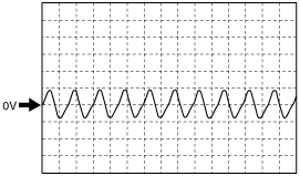
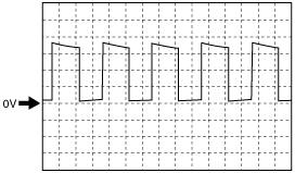
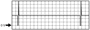
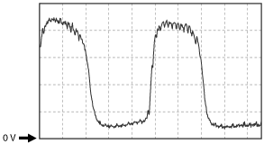
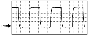
Inspection Using An Oscilloscope (Reference)
Input/turbine speed sensor signal
am2zzw00004572
|
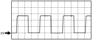
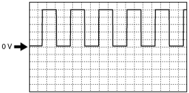
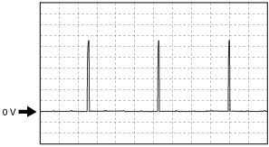
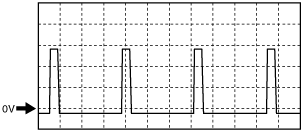
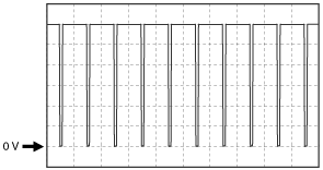
Vehicle speed output signal
am2zzw00004573
|
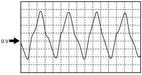
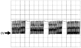
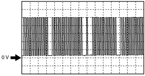
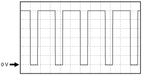
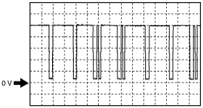
Vehicle speed (+) signal (MTX)
am2zzw00004574
|
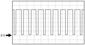
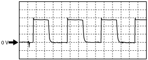
Pressure control solenoid (–) signal
am2zzw00004785
|
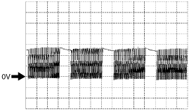
Vehicle speed signal (ATX)
am2zzw00004577
|
Shift solenoid A signal
am2zzw00004578
|
Shift solenoid C signal
am2zzw00004579
|
Shift solenoid B signal
am2zzw00004580
|
Fuel injection control signal
am2zzw00004581
|
ESA control signal
am2zzw00004582
|
CKP signal
am2zzw00004583
|
IAC (–) signal
am2zzw00004584
|
Oxygen concentration signal
am2zzw00004585
|
Variable valve timing control (+) signal
am2zzw00004586
|
HO2S heater signal
am2zzw00004587
|
Generator control signal
am2zzw00004588
|
Generator output voltage signal
am2zzw00004589
|
Purge control signal
am2zzw00004590
|
CMP signal
am2zzw00004591
|