THROTTLE POSITION (TP) SENSOR INSPECTION
id014000802700
-
Note
-
• Perform the following inspection according to the DATA MONITOR function (indicated by monitor item from here onwards).
Resistance Inspection
1. Verify the following.
-
• Throttle valve closed status
-
• Accelerator cable play
-
- If the monitor item condition/specification (reference) is not within the specification, even though there is no malfunction, perform the following resistance inspection.
2. Disconnect the negative battery cable.
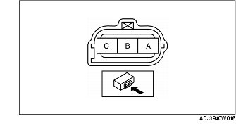
3. Disconnect the TP sensor connector.
4. Verify that the resistance between terminals B and C changes moderately corresponding to the throttle valve opening.
-
• If the resistance change is verified, go to the next step.
-
• If the resistance change is not verified, replace the TP sensor.
5. Measure the resistance between terminals A and B.
-
• If not within the specification, replace the TP sensor.
-
• If the monitor item condition/specification (reference) is not within the specification, even though the resistance is within the specification, carry out the "Circuit Open/Short Inspection".
Resistance
-
2.5-6.0 kilohms [25°C {77 °F}]
Circuit Open/Short Inspection
1. Inspect the following wiring harnesses for an open or short circuit. (Continuity check)
Open circuit
-
• If there is no continuity, the circuit is open. Repair or replace the wiring harness.
-
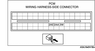
- TP sensor terminal A and PCM terminal 2W
-
- TP sensor terminal B and PCM terminal 2AE
-
- TP sensor terminal C and PCM terminal 2AA
Short circuit
-
• If there is continuity, the circuit is shorted. Repair or replace the wiring harness.
-
- TP sensor terminal A and body GND
-
- TP sensor terminal B and power supply
-
- TP sensor terminal C and power supply
-
- TP sensor terminal C and body GND