|
STEP
|
INSPECTION
|
ACTION
|
|
1
|
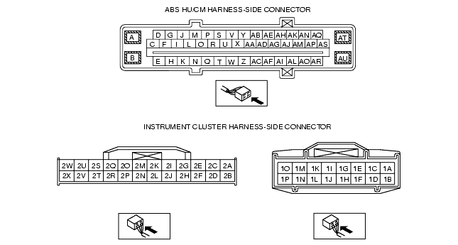
INSPECT WIRING HARNESS BETWEEN ABS HU/CM AND DLC-2 (DATA LINK CONNECTOR-2) FOR CONTINUITY AND SHORTS
• Perform DTC inspection.
• Is error message displayed regarding communication between ABS HU/CM and WDS or equivalent?
|
Yes
|
If the communication error message is displayed even after inspecting according to procedures displayed in the WDS or equivalent, go to Step 4.
|
|
No
|
Go to next step.
|
|
2
|
CHECK FOR DTCs IN ABS HU/CM
• Have DTCs been recorded in memory?
|
Yes
|
Perform inspection using appropriate DTC.
|
|
No
|
Inspect instrument cluster
If instrument cluster is OK, then go to next step.
If instrument cluster malfunction, repair instrument cluster, then go to next step.
|
|
3
|
INSPECT WIRING HARNESS BETWEEN ABS HU/CM AND DLC-2 (DATA LINK CONNECTOR-2) FOR CONTINUITY
• Disconnect ABS HU/CM connector.
• Is there continuity between connector terminal AQ and data link connector?
|
Yes
|
Go to next step.
|
|
No
|
Repair wiring harness between ABS HU/CM and data link connector.
|
|
*4
|
INSPECT WIRING HARNESS BETWEEN ABS HU/CM AND DLC-2 (DATA LINK CONNECTOR-2) FOR SHORT TO B+
• Is voltage approx. 12V at connector terminal AQ?
|
Yes
|
Repair wiring harness between ABS HU/CM and data link connector.
|
|
No
|
Go to next step.
|
|
5
|
INSPECT WIRING HARNESS BETWEEN ABS HU/CM AND DLC-2 (DATA LINK CONNECTOR-2) FOR SHORT TO GROUND
Is there continuity between connector terminal AQ and ground?
|
Yes
|
Repair wiring harness between ABS HU/CM and data link connector.
|
|
No
|
Replace ABS CM (communication circuit malfunction is ABS CM).
|
|
|