Diagnostic procedure
|
STEP
|
INSPECTION
|
ACTION
|
|
|---|---|---|---|
|
1
|
VERIFY FREEZE FRAME DATA HAS BEEN RECORDED
• Has FREEZE FRAME PID DATA been recorded?
|
Yes
|
Go to next step.
|
|
No
|
Record FREEZE FRAME PID DATA on repair order, then go to next step.
|
||
|
2
|
VERIFY RELATED REPAIR INFORMATION AVAILABILITY
• Check for related Service Bulletins availability.
• Is any related repair information available?
|
Yes
|
Perform repair or diagnosis according to available repair information.
• If vehicle is not repaired, go to next step.
|
|
No
|
Go to next step.
|
||
|
3
|
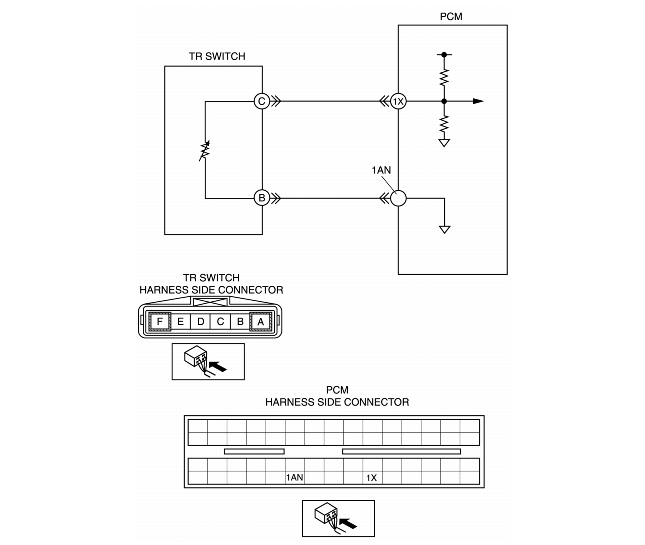
INSPECT TR SWITCH CONNECTOR FOR POOR CONNECTION
• Turn ignition key OFF.
• Disconnect TR switch connector.
• Check for poor connection (damaged/pulled-out pins, corrosion, etc.).
• Are TR switch terminals normal?
|
Yes
|
Go to next step.
|
|
No
|
Repair terminals or replace TR switch, then go to Step 9.
|
||
|
4
|
INSPECT TR SWITCH
• Turn the ignition switch off.
• Disconnect TR switch connector.
• Inspect for resistance between TR switch terminals B and C (part-side).
• Is resistance normal?
|
Yes
|
Go to next step.
|
|
No
|
Adjust TR switch, then go to Step 9.
|
||
|
5
|
INSPECT TR SWITCH SIGNAL CIRCUIT FOR SHORT TO POWER
• Turn the ignition switch to the ON position (Engine OFF).
• Measure the voltage between TR switch terminal C (harness-side) and body ground.
• Is there voltage B+?
|
Yes
|
Repair or replace harness for short to power, then go to step 9.
|
|
No
|
Go to next step.
|
||
|
6
|
INSPECT PCM CONNECTOR FOR POOR CONNECTION
• Disconnect PCM connector.
• Check for poor connection at terminals 1X and 1AN (damaged/pulled-out pins, corrosion, etc.).
• Is there any malfunction?
|
Yes
|
Repair or replace terminal, then go to step 9.
|
|
No
|
Go to next step.
|
||
|
7
|
INSPECT TR SWITCH SIGNAL CIRCUIT FOR OPEN CIRCUIT
• Check for continuity between TR switch terminal C (harness-side) and PCM terminal 1X.
• Is there continuity?
|
Yes
|
Go to next step.
|
|
No
|
Repair or replace harness for open, then go to step 9.
|
||
|
8
|
INSPECT TR SWITCH GROUND CIRCUIT FOR OPEN CIRCUIT
• Check for continuity between TR switch terminal B (harness-side) and PCM terminal 1AN.
• Is there continuity?
|
Yes
|
Go to next step.
|
|
No
|
Repair or replace harness for open, then go to next step.
|
||
|
9
|
VERIFY TROUBLESHOOTING OF DTC P0708 COMPLETED
• Make sure to reconnect all disconnected connectors.
• Clear DTC from memory using WDS or equivalent.
• Drive vehicle for 100 s or more under following conditions.
• Is pending code present?
|
Yes
|
Replace PCM, then go to next step.
(See PCM REMOVAL/INSTALLATION.)
|
|
No
|
No concern is detected. Go to next step.
|
||
|
10
|
VERIFY AFTER REPAIR PROCEDURE
• Perform "After Repair Procedure".
• Are any DTCs present?
|
Yes
|
Go to applicable DTC inspection.
|
|
No
|
Troubleshooting completed.
|
||