Diagnostic procedure
|
STEP
|
INSPECTION
|
ACTION
|
|
|---|---|---|---|
|
1
|
VERIFY FREEZE FRAME DATA HAS BEEN RECORDED
• Has FREEZE FRAME PID DATA been recorded?
|
Yes
|
Go to next step.
|
|
No
|
Record FREEZE FRAME PID DATA on repair order, then go to next step.
|
||
|
2
|
VERIFY RELATED REPAIR INFORMATION AVAILABILITY
• Check for related Service Bulletins availability.
• Is any related repair information available?
|
Yes
|
Perform repair or diagnosis according to available repair information.
• If vehicle is not repaired, go to next step.
|
|
No
|
Go to next step.
|
||
|
3
|
VERIFY CURRENT INPUT SIGNAL STATUS
• Turn the ignition switch off.
• Start engine.
• Measure frequency of input/turbine speed sensor using a oscilloscope.
• Are frequency of input/turbine speed sensor readings within specifications?
|
Yes
|
Go to intermittent concern troubleshooting procedure.
|
|
No
|
Go to next step.
|
||
|
4
|
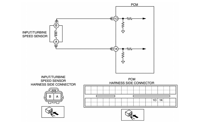
INSPECT INPUT/TURBINE SPEED SENSOR CONNECTOR FOR POOR CONNECTION
• Turn the ignition switch off.
• Disconnect input/turbine speed sensor connector.
• Check for poor connection (damaged/pulled-out terminals, corrosion, etc.).
• Is connection normal?
|
Yes
|
Go to next step.
|
|
No
|
Repair or replace connector and/or terminals, then go to Step 10.
|
||
|
5
|
INSPECT INPUT/TURBINE SPEED SENSOR RESISTANCE
• Measure resistance between input/turbine speed sensor terminals (part-side).
• Is resistance within 250-600 ohms between input/turbine speed sensor terminals (part-side)?
|
Yes
|
Go to next step.
|
|
No
|
Replace input/turbine speed sensor, then go to Step 10.
|
||
|
6
|
INSPECT INPUT/TURBINE SPEED SENSOR
• Remove input/turbine speed sensor.
• Is there iron powder stuck on input/turbine speed sensor?
|
Yes
|
Clean input/turbine speed sensor, then go to Step 10.
|
|
No
|
Go to next step.
|
||
|
7
|
INSPECT PCM CONNECTOR FOR POOR CONNECTION
• Disconnect PCM connector.
• Check for poor connection (damaged/pulled-out terminals, corrosion, etc.).
• Is connection normal?
|
Yes
|
Go to next step.
|
|
No
|
Repair or replace connector and/or terminals, then go to Step 10.
|
||
|
8
|
INSPECT INPUT/TURBINE SPEED SENSOR CIRCUIT FOR OPEN
• Inspect input/turbine speed sensor terminals (harness-side) and PCM terminals (harness-side).
• Is there continuity?
|
Yes
|
Go to next step.
|
|
No
|
Repair or replace harness, then go to Step 10.
|
||
|
9
|
INSPECT INPUT/TURBINE SPEED SENSOR CIRCUIT FOR SHORT TO GROUND
• Inspect input/turbine speed sensor terminal (harness-side) and body ground.
• Is there continuity?
|
Yes
|
Repair or replace harness, then go to next step.
|
|
No
|
Go to next step.
|
||
|
10
|
VERIFY TROUBLESHOOTING OF DTC P0715 COMPLETED
• Make sure to reconnect all disconnected connectors.
• Clear DTC from memory using WDS or equivalent.
• Drive vehicle with vehicle speed 40 km/h
{25 mph} or above for 0.7 s or more.
• Is same DTC present?
|
Yes
|
Replace PCM, then go to next step.
(See PCM REMOVAL/INSTALLATION.)
|
|
No
|
Go to next step.
|
||
|
11
|
VERIFY AFTER REPAIR PROCEDURE
• Perform "After Repair Procedure".
• Are any DTCs present?
|
Yes
|
Go to applicable DTC inspection.
|
|
No
|
Troubleshooting completed.
|
||