 |
am2zzw00007274
VEHICLE SPEEDOMETER SENSOR (VSS) INSPECTION [WITHOUT ABS]
id0517a12650b7
Visual Inspection
1. Remove the VSS. (See VEHICLE SPEEDOMETER SENSOR (VSS) REMOVAL/INSTALLATION [WITHOUT ABS].)
2. Make sure that the sensor is free of any metallic shavings or particles.
3. Install the VSS. (See VEHICLE SPEEDOMETER SENSOR (VSS) REMOVAL/INSTALLATION [WITHOUT ABS].)
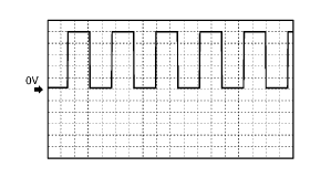
Wave profile Inspection
1. Remove the PCM. (See PCM REMOVAL/INSTALLATION.)
2. Connect WDS or equivalent to DLC-2.
3. Connect oscilloscope test leads to the following PCM connector terminals.
4. Start the engine.
5. Monitor VSS PID.
6. Inspect wave profile.
am2zzw00007274
|
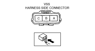
Power Supply Voltage Inspection
1. Disconnect the VSS connector.
2. Turn the ignition switch to ON.
3. Measure voltage at VSS connector terminal A (wiring harness side).
am2zzw00007275
|
Open Circuit Inspection
1. Inspect the following circuit for open.
Short Circuit Inspection
1. Inspect the following circuit for short.
am2zzw00007275
|
Sensor Rotor Inspection
1. Remove the VSS. (See VEHICLE SPEEDOMETER SENSOR (VSS) REMOVAL/INSTALLATION [WITHOUT ABS].)
2. Shift the selector lever to N position.
3. Inspect sensor rotor surface via VSS installation hole while rotating the front tire manually.