 |
bezeze00000077
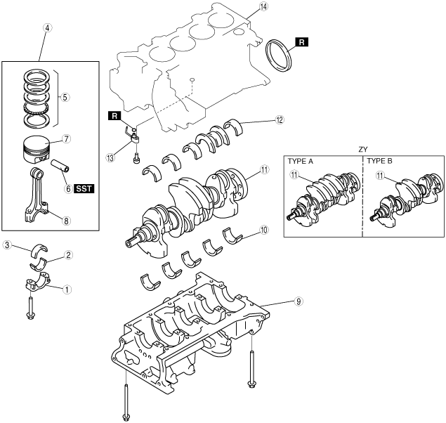
CYLINDER BLOCK DISASSEMBLY (II)
id011000500700
1. Disassemble in the order indicated in the table.
bezeze00000077
|
|
1
|
Connecting rod cap
|
|
2
|
Lower connecting rod bearing
|
|
3
|
Upper connecting rod bearing
|
|
4
|
Connecting rod, piston assembly
|
|
5
|
Piston ring
|
|
6
|
Piston pin
|
|
7
|
Piston
|
|
8
|
Connecting rod
|
|
9
|
Lower cylinder block
|
|
10
|
Lower main bearing
|
|
11
|
Crankshaft
|
|
12
|
Upper main bearing
|
|
13
|
Oil jet valve
|
|
14
|
Upper cylinder block
|
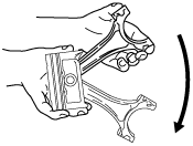
Connecting Rod Cap Disassembly Note
1. Inspect the connecting rod side clearance. (See CONNECTING ROD INSPECTION.)
b3e0110e087
|
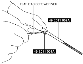
Piston Pin Disassembly Note
1. Before extracting the piston pin, inspect the following.
bezuue00000097
|
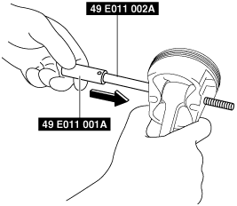
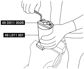
2. Assemble the SSTs to the piston using the following procedures.
bezuue00000141
|
bezuue00000134
|
bezuue00000135
|
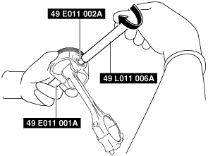
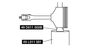
3. Assemble the SST (49 D011 002B) to the SST (49 L011 001).
bezuue00000136
|
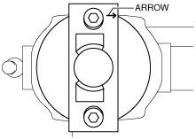
4. Set the piston assembled with the SST on the SST (49 D011 002B) horizontally. At this time, set the piston head so that it is facing the direction of the arrow on the SST (49 D001 002B).
bezuue00000100
|
bezuue00000142
|
5. Press out the piston pin using the hydraulic press.
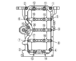
Lower Cylinder Block Disassembly Note
1. Inspect the crankshaft end play. (See CRANKSHAFT INSPECTION.)
2. Loosen the lower cylinder block installation bolts in the order shown in the figure.
bezeze00000078
|