|
bezeze00000019
CYLINDER BLOCK ASSEMBLY (II)
id011000504100
1. Assemble in the order indicated in the table.
bezeze00000019
|
|
1
|
Oil pump body
|
|
2
|
Control plunger
|
|
3
|
Plunger spring
|
|
4
|
Plunger plug
|
|
5
|
Outer rotor
|
|
6
|
Inner rotor
|
|
7
|
Oil pump cover
|
|
8
|
Oil strainer
|
|
9
|
Oil pan
(See Oil Pan Assembly Note.)
|
|
10
|
Oil filter joint
(See Oil Filter Assembly Note.)
|
|
11
|
Oil cooler
(See Oil Filter Assembly Note.)
|
|
12
|
Oil filter
(See Oil Filter Assembly Note.)
|
|
13
|
Rear oil seal
(See Rear Oil Seal Assembly Note.)
|
|
14
|
End plate
|
|
15
|
Drive plate (ATX), flywheel (MTX)
|
|
16
|
Oil pump
(See Oil Pump Assembly Note.)
|
|
17
|
Water pump
|
|
18
|
Oil separator
|
|
19
|
Knock sensor
(See Knock Sensor Assembly Note.)
|
|
20
|
Thermostat
|
|
21
|
Thermostat cover
|
Inner Rotor, Outer Rotor Assembly Note
1. Assemble the inner rotor and the outer rotor with the punch marks aligned.
bezeze00000020
|
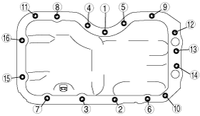
Oil Pan Assembly Note
1. Apply silicone sealant as shown in the figure.
bezeze00000021
|
2. Tighten the oil pan installation bolts in the order shown in the figure.
bezeze00000022
|
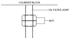
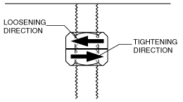
Oil Filter Joint Assembly Note
1. Install the oil filter joint using the following procedure:
bezeze00000031
|
bezeze00000032
|
bezeze00000033
|
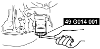
Oil Cooler Installation Note
1. Install the oil cooler so that the mark on it is oriented towards the vehicle front.
bezeze00000034
|
2. Hold the oil cooler by hand.
3. Tighten the oil cooler mounting nut.
Oil Filter Assembly Note
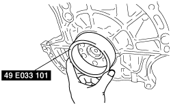
1. Install the oil filter using the SST.
bezeze00000023
|
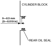
Rear Oil Seal Assembly Note
1. Apply clean engine oil to a new rear oil seal.
2. Insert the rear oil seal to the cylinder block by hand.
3. Install the rear oil seal using the SST.
bezeze00000024
|
bezeze00000025
|
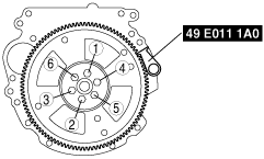
Drive Plate (ATX), Flywheel (MTX) Assembly Note
1. Lock the drive plate (ATX) or flywheel (MTX) against rotation using the SST.
bezeze00000026
|
2. Tighten the flywheel installation bolts in two to three passes in the order shown in the figure.
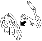
Oil Pump Assembly Note
1. Install the gasket to the oil pump.
bezeze00000027
|
2. Install the oil pump and gasket as a single unit.
Knock Sensor Assembly Note
1. Install the knock sensor using the SST.
bezeze00000028
|