 |
bezeze00000053
TIMING CHAIN ASSEMBLY
id011000505600
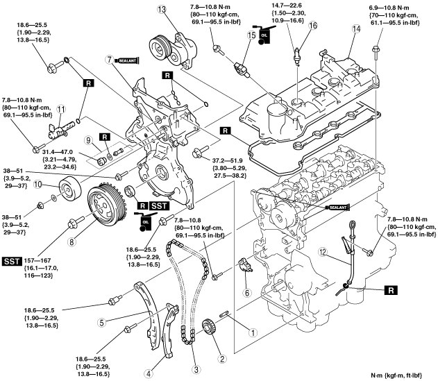
1. Assemble in the order indicated in the table.
bezeze00000053
|
|
1
|
Key
|
|
2
|
Crankshaft sprocket
|
|
3
|
Timing chain
|
|
4
|
Timing chain guide
|
|
5
|
Timing chain tensioner arm
|
|
6
|
Timing chain tensioner
|
|
7
|
Engine front cover
|
|
8
|
Crankshaft pulley
|
|
9
|
OCV oil filter, plug
|
|
10
|
Idler pulley
|
|
11
|
OCV
|
|
12
|
Oil level gauge pipe
|
|
13
|
Drive belt auto tensioner
|
|
14
|
Cylinder head cover
|
|
15
|
CMP sensor
(See CMP Sensor Assembly Note.)
|
|
16
|
Spark plug
|
Timing Chain Assembly Note
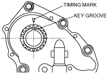
1. Align the key groove of the crankshaft sprocket to the timing mark, and then position the No.1 cylinder to TDC.
bezeze00000042
|
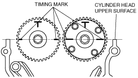
2. Align the timing marks on the camshaft sprockets so that they form a straight line in alignment with the upper horizontal surface of the cylinder head.
bezeze00000043
|
3. Install the timing chain.
4. Install the timing chain guide and timing chain tensioner arm.
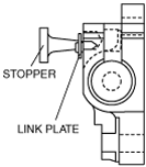
5. Install the chain adjuster and then remove the wire or paper clip used for fixing. (Remove the installed stopper when installing the new chain tensioner.)
bezeze00000044
|
6. Verify that there is no slack on the timing chain and then verify that each sprocket is positioned in the proper place again.
7. Inspect the valve timing by rotating the crankshaft clockwise twice.
Engine Front Cover Assembly Note
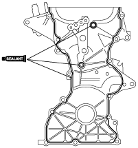
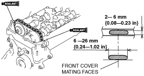
1. Apply silicone sealant to the engine front cover as shown in the figure.
bezeze00000045
|
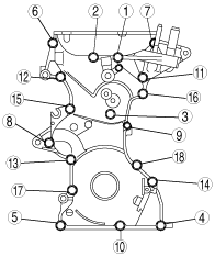
2. Tighten the engine front cover installation bolts in the order shown in the figure.
bezeze00000046
|
|
Position
|
Tightening torque
|
|
9
|
7.8—10.8 N·m {80—110 kgf·cm, 69.1—95.5 in·lbf}
|
|
1—6, 8, 10, 12—15, 17, 18
|
18.6—25.5 N·m {1.90—2.29 kgf·m, 13.8—16.5 ft·lbf}
|
|
7, 11, 16
|
37.2—51.9 N·m {3.80—5.29 kgf·m, 27.5—38.2 ft·lbf}
|
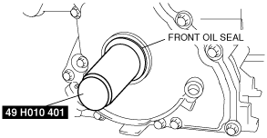
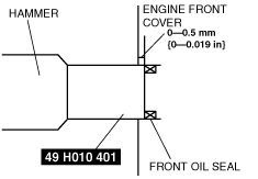
3. Install the oil seal using the SST.
bezeze00000047
|
bezeze00000048
|
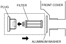
4. Install the oil filter to the plug and insert it in the front cover as shown in the figure.
bezeze00000049
|
Crankshaft Pulley Installation Bolt Assembly Note
1. Lock the drive plate (ATX) or flywheel (MTX) against rotation using the SST.
bezeze00000050
|
2. Tighten the crankshaft pulley installation bolt.
Cylinder Head Cover Assembly Note
1. Apply silicone sealant as shown in the figure.
bezeze00000051
|
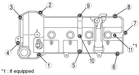
2. Tighten the cylinder head cover installation bolts in the order shown in the figure.
bezeze00000052
|
CMP Sensor Assembly Note
1. Verify that the O-ring is not damaged.
2. Apply a small amount of clean oil to the O-ring and the cylinder head cover.