DTC P0703:00 [MZR 1.3, MZR 1.5]
id0102f8706500
DTC P0703:00 |
Brake switch input circuit problem |
---|---|
DETECTION CONDITION
|
• The PCM monitors the input signal from the brake switch No.1. If the input signal does not change while following decelerating 8 times, the PCM determines that there is a brake switch No.1 input circuit problem.
MONITORING CONDITIONS
Diagnostic support note
• This is a continuous monitor (CCM).
• The MIL illuminates if the PCM detects the above malfunction condition in two consecutive drive cycles or in one drive cycle while the DTC for the same malfunction has been stored in the PCM.
• PENDING CODE is available if the PCM detects the above malfunction condition during first drive cycle.
• FREEZE FRAME DATA (Mode 2)/Snapshot data is available.
• The DTC is stored in the PCM memory.
|
POSSIBLE CAUSE
|
• Brake switch connector or terminals malfunction
• Short to ground or open circuit in brake switch No.1 power supply circuit
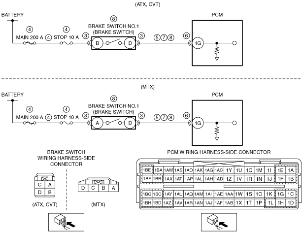
• Short to ground in wiring harness between brake switch terminal D and PCM terminal 1G
• PCM connector or terminals malfunction
• Short to power supply in wiring harness between brake switch terminal D and PCM terminal 1G
• Open circuit in wiring harness between brake switch terminal D and PCM terminal 1G
• Brake switch No.1 malfunction
• PCM malfunction
|
![]() |
Diagnostic procedure
STEP |
INSPECTION |
ACTION |
|
---|---|---|---|
1
|
VERIFY FREEZE FRAME DATA (MODE 2)/SNAPSHOT DATA HAS BEEN RECORDED
• Has the FREEZE FRAME DATA (Mode 2)/snapshot data been recorded?
|
Yes
|
Go to the next step.
|
No
|
Record the FREEZE FRAME DATA (Mode 2)/snapshot data on the repair order, then go to the next step.
|
||
2
|
VERIFY RELATED SERVICE INFORMATION AVAILABILITY
• Verify related Service Information availability.
• Is any related Service Information available?
|
Yes
|
Perform repair or diagnosis according to the available Service Information.
• If the vehicle is not repaired, go to the next step.
|
No
|
Go to the next step.
|
||
3
|
INSPECT BRAKE SWITCH CONNECTOR CONDITION
• Turn the ignition switch off.
• Disconnect the brake switch connector.
• Inspect for poor connection (such as damaged/pulled-out pins, corrosion).
• Is there any malfunction?
|
Yes
|
Repair or replace the connector and/or terminals, then go to Step 9.
|
No
|
Go to the next step.
|
||
4
|
INSPECT BRAKE SWITCH NO.1 POWER SUPPLY CIRCUIT FOR SHORT TO GROUND OR OPEN CIRCUIT
• Brake switch connector is disconnected.
• Measure the voltage at the brake switch terminal B (wiring harness-side). (ATX, CVT)
• Measure the voltage at the brake switch terminal A (wiring harness-side). (MTX)
• Is the voltage B+?
|
Yes
|
Go to the next step.
|
No
|
Inspect the MAIN 200 A fuse and STOP 10 A fuse.
• If the fuse is melted:
• If the fuse is deteriorated:
• If all fuses are normal:
Go to Step 9.
|
||
5
|
INSPECT BRAKE SWITCH NO.1 SIGNAL CIRCUIT FOR SHORT TO GROUND
• Brake switch connector is disconnected.
• Inspect for continuity between brake switch terminal D (wiring harness-side) and body ground.
• Is there continuity?
|
Yes
|
If the short to ground circuit could be detected:
• Repair or replace the wiring harness for a possible short to ground.
If the short to ground circuit could not be detected:
• Replace the PCM (short to ground in the PCM internal circuit).
Go to Step 9.
|
No
|
Go to the next step.
|
||
6
|
INSPECT PCM CONNECTOR CONDITION
• Disconnect the PCM connector.
• Inspect for poor connection (such as damaged/pulled-out pins, corrosion).
• Is there any malfunction?
|
Yes
|
Repair or replace the connector and/or terminals, then go to Step 9.
|
No
|
Go to the next step.
|
||
7
|
INSPECT BRAKE SWITCH NO.1 SIGNAL CIRCUIT FOR SHORT TO POWER SUPPLY
• Brake switch and PCM connectors are disconnected.
• Turn the ignition switch to the ON position (engine off).
• Measure the voltage at the brake switch terminal D (wiring harness-side).
• Is there any voltage?
|
Yes
|
Repair or replace the wiring harness for a possible short to power supply, then go to Step 9.
|
No
|
Go to the next step.
|
||
8
|
INSPECT BRAKE SWITCH NO.1 SIGNAL CIRCUIT FOR OPEN CIRCUIT
• Brake switch and PCM connectors are disconnected.
• Turn the ignition switch off.
• Inspect for continuity between brake switch terminal D (wiring harness-side) and PCM terminal 1G (wiring harness-side).
• Is there continuity?
|
Yes
|
Replace the brake switch, then go to the next step.
|
No
|
Repair or replace the wiring harness for a possible open circuit, then go to the next step.
|
||
9
|
VERIFY DTC TROUBLESHOOTING COMPLETED
• Make sure to reconnect all disconnected connectors.
• Clear the DTC from the PCM memory using the M-MDS.
• Drive the vehicle.
• Repeat deceleration 8 times under both of the following conditions:
• Perform the Pending Trouble Code Access Procedure.
• Is the PENDING CODE for this DTC present?
|
Yes
|
Repeat the inspection from Step 1.
• If the malfunction recurs, replace the PCM.
Go to the next step.
|
No
|
Go to the next step.
|
||
10
|
VERIFY AFTER REPAIR PROCEDURE
• Perform the “AFTER REPAIR PROCEDURE”.
• Are any DTCs present?
|
Yes
|
Go to the applicable DTC inspection.
(See DTC TABLE [MZR 1.3, MZR 1.5].)
|
No
|
DTC troubleshooting completed.
|