|
1
|
VERIFY FREEZE FRAME DATA (MODE 2)/SNAPSHOT DATA HAS BEEN RECORDED
• Has the FREEZE FRAME DATA (Mode 2)/snapshot data been recorded?
|
Yes
|
Go to the next step.
|
|
No
|
Record the FREEZE FRAME DATA (Mode 2)/snapshot data on the repair order, then go to the next step.
|
|
2
|
VERIFY RELATED SERVICE INFORMATION AVAILABILITY
• Verify related Service Information availability.
• Is any related Service Information available?
|
Yes
|
Perform repair or diagnosis according to the available Service Information.
• If the vehicle is not repaired, go to the next step.
|
|
No
|
Go to the next step.
|
|
3
|
VERIFY RELATED PENDING CODE AND/OR DTC
• Turn the ignition switch off, then to the ON position (engine off).
• Perform the Pending Trouble Code Access Procedure and DTC Reading Procedure.
• Are any other PENDING CODEs and/or DTCs present?
|
Yes
|
Go to the applicable PENDING CODE or DTC inspection.
|
|
No
|
Go to the next step.
|
|
4
|
INSPECT PCM CONNECTOR CONDITION
• Turn the ignition switch off.
• Disconnect the PCM connector.
• Inspect for poor connection (such as damaged/pulled-out pins, corrosion).
• Is there any malfunction?
|
Yes
|
Repair or replace the connector and/or terminals, then go to Step 12.
|
|
No
|
Go to the next step.
|
|
5
|
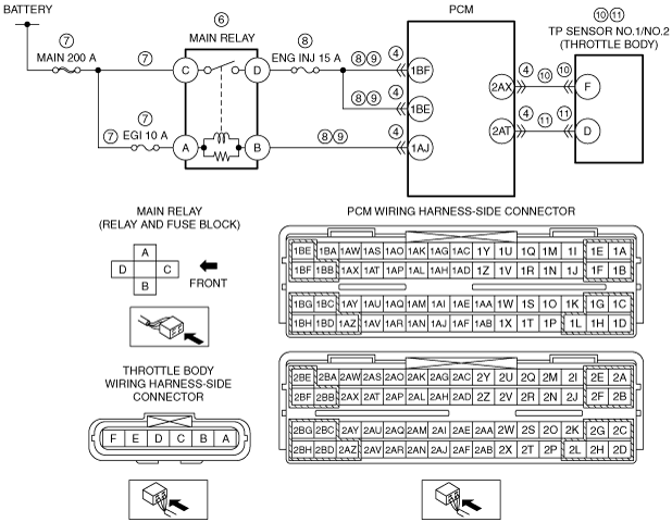
INSPECT MAIN RELAY OUTPUT VOLTAGE
• PCM connector is disconnected.
• Turn the ignition switch to the ON position (engine off).
• Measure the voltage at the following terminals (wiring harness-side):
-
― PCM terminal 1BF
― PCM terminal 1BE
• Is the voltage B+?
|
Yes
|
Go to Step 10.
|
|
No
|
Go to the next step.
|
|
6
|
INSPECT MAIN RELAY
• Turn the ignition switch off.
• Remove the main relay.
• Inspect the main relay.
• Is there any malfunction?
|
Yes
|
Replace the main relay, then go to Step 12.
|
|
No
|
Go to the next step.
|
|
7
|
INSPECT MAIN RELAY POWER SUPPLY CIRCUIT FOR SHORT TO GROUND OR OPEN CIRCUIT
• Main relay is removed.
• PCM connector is disconnected.
• Measure the voltage at the following terminals (wiring harness-side):
-
― Main relay terminal C
― Main relay terminal A
• Is the voltage B+?
|
Yes
|
Reinstall the main relay, then go to the next step.
|
|
No
|
If the main relay terminal C voltage is not normal:
• Inspect the MAIN 200 A fuse.
-
― If the fuse is melted:
-
• Repair or replace the wiring harness for a possible short to ground.
• Replace the fuse.
― If the fuse is deteriorated:
-
• Replace the fuse.
― If the fuse is normal:
-
• Repair or replace the wiring harness for a possible open circuit.
If the main relay terminal A voltage is not normal:
• Inspect the MAIN 200 A fuse and EGI 10 A fuse.
-
― If the fuse is melted:
-
• Repair or replace the wiring harness for a possible short to ground.
• Replace the malfunctioning fuse.
― If the fuse is deteriorated:
-
• Replace the malfunctioning fuse.
― If all fuses are normal:
-
• Repair or replace the wiring harness for a possible open circuit.
Go to Step 12.
|
|
8
|
INSPECT MAIN RELAY CONTROL CIRCUIT FOR SHORT TO GROUND OR OPEN CIRCUIT
• PCM connector is disconnected.
• Turn the ignition switch to the ON position (engine off).
• Measure the voltage at the following terminals (wiring harness-side):
-
― PCM terminal 1BF
― PCM terminal 1BE
― PCM terminal 1AJ
|
Yes
|
Go to the next step.
|
|
No
|
If the PCM terminal 1BF and/or 1BE voltage is not normal:
• Inspect the ENG INJ 15 A fuse.
-
― If the fuse is melted:
-
• Repair or replace the wiring harness for a possible short to ground.
• Replace the fuse.
― If the fuse is deteriorated:
-
• Replace the fuse.
― If the fuse is normal:
-
• Repair or replace the wiring harness for a possible open circuit.
If the PCM terminal 1AJ voltage is not normal:
• Repair or replace the wiring harness for a possible short to ground or open circuit.
Go to Step 12.
|
|
9
|
INSPECT MAIN RELAY CONTROL CIRCUIT FOR SHORT TO POWER SUPPLY
• PCM connector is disconnected.
• Turn the ignition switch off.
• Remove the main relay.
• Turn the ignition switch to the ON position (engine off).
• Measure the voltage at the following terminals (wiring harness-side):
-
― Main relay terminal D
― Main relay terminal B
• Is there any voltage?
|
Yes
|
Repair or replace the wiring harness for a possible short to power supply, then go to Step 12.
|
|
No
|
Go to the next step.
|
|
10
|
INSPECT TP SENSOR NO.1
• Reconnect all disconnected connectors.
• Inspect the TP sensor No.1.
• Is there any malfunction?
|
Yes
|
Inspect the TP sensor No.1 related circuits and connectors.
• If there is any malfunction:
-
― Repair or replace the malfunctioning part according to the inspection results.
• If there is no malfunction:
-
― Replace the throttle body.
Go to Step 12.
|
|
No
|
Go to the next step.
|
|
11
|
INSPECT TP SENSOR NO.2
• Inspect the TP sensor No.2.
• Is there any malfunction?
|
Yes
|
Inspect the TP sensor No.2 related circuits and connectors.
• If there is any malfunction:
-
― Repair or replace the malfunctioning part according to the inspection results.
• If there is no malfunction:
-
― Replace the throttle body.
Go to the next step.
|
|
No
|
Go to the next step.
|
|
12
|
VERIFY DTC TROUBLESHOOTING COMPLETED
• Make sure to reconnect all disconnected connectors.
• Clear the DTC from the PCM memory using the M-MDS.
• Perform the KOER self test.
• Is the same DTC present?
|
Yes
|
Repeat the inspection from Step 1.
• If the malfunction recurs, replace the PCM.
Go to the next step.
|
|
No
|
Go to the next step.
|
|
13
|
VERIFY AFTER REPAIR PROCEDURE
• Perform the “AFTER REPAIR PROCEDURE”.
• Are any DTCs present?
|
Yes
|
Go to the applicable DTC inspection.
|
|
No
|
DTC troubleshooting completed.
|