 |
am2zzw00006224
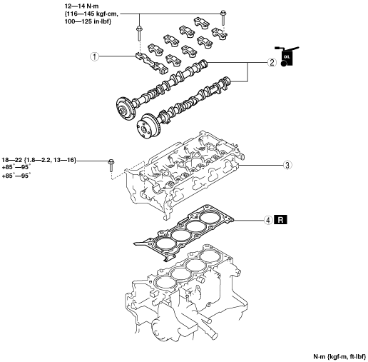
CYLINDER HEAD GASKET REPLACEMENT [MZR 1.3, MZR 1.5]
id0110e1800700
1. Remove the timing chain. (See TIMING CHAIN REMOVAL/INSTALLATION [MZR 1.3, MZR 1.5].)
2. Set the exhaust manifold out of the way. (See EXHAUST SYSTEM REMOVAL/INSTALLATION [MZR 1.3, MZR 1.5].)
3. Remove the intake manifold. (See INTAKE-AIR SYSTEM REMOVAL/INSTALLATION [MZR 1.3, MZR 1.5].)
4. Disconnect the heater hose and radiator hose.
5. Remove in the order indicated in the table.
6. Install in the reverse order of removal.
7. Inspect the compression. (See COMPRESSION INSPECTION [MZR 1.3, MZR 1.5].)
am2zzw00006224
|
|
1
|
Camshaft cap
(See Camshaft Cap Removal Note.)
|
|
2
|
Camshaft
|
|
3
|
Cylinder head
(See Cylinder Head Removal Note.)
|
|
4
|
Cylinder head gasket
|
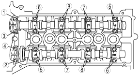
Camshaft Cap Removal Note
1. Loosen the camshaft cap installation bolts in two or three steps in the order shown in the figure, and remove them.
am2zzw00006225
|
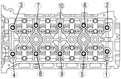
Cylinder Head Removal Note
1. Loosen the cylinder head installation bolts in two or three steps in the order shown in the figure, and remove them.
am2zzw00001764
|
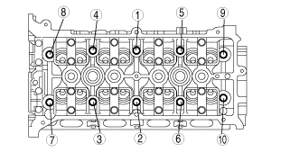
Cylinder Head Installation Note
1. Measure the length of each cylinder head installation bolt.
am2zzw00001765
|
2. Tighten the cylinder head installation bolts in three steps in the order shown in the figure.
am2zzw00000082
|
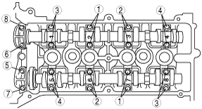
Camshaft Cap Installation Note
1. Align the No.1 cylinder camshaft position to the TDC position, and install the camshaft.
2. Install the camshaft caps to the position of a carved seal number to shown in the figure, and tighten the camshaft installation bolts in two or three steps uniformly in the order shown in the figure.
am2zzw00006226
|