 |
acmzzw00000118
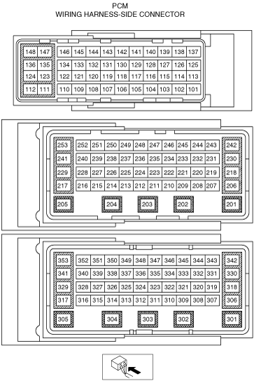
PCM INSPECTION [MZ-CD 1.6]
id0140e7802500
Specification identification
acmzzw00000118
|
Without Using the SST
am2zzw00006316
|
PCM terminal voltage table (Reference)
|
Terminal |
Signal name |
Connected to |
Measurement condition |
Voltage (V) |
Inspection item(s) |
|
|---|---|---|---|---|---|---|
|
101
|
—
|
|||||
|
102
|
EGR valve position sensor supply
|
EGR valve position sensor
|
Switch the ignition ON
|
Approx. 5.0
|
• Related wiring harness
• EGR valve
|
|
|
103
|
Intake shutter valve position sensor supply
|
Intake shutter valve position sensor
|
Switch the ignition ON
|
Approx. 5.0
|
• Related wiring harness
• Intake shutter valve
|
|
|
104
|
—
|
|||||
|
105
|
—
|
|||||
|
106
|
—
|
|||||
|
107
|
—
|
|||||
|
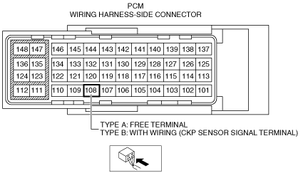
108
|
Type A
|
|||||
|
—
|
||||||
|
Type B
CKP sensor signal
|
CKP sensor
|
Inspect using the wave Profile. (See Inspection Using An Oscilloscope (Reference).)
|
• Related wiring harness
• CKP sensor
|
|||
|
109
|
MAF sensor signal
|
MAF/IAT sensor
|
Inspect using the wave Profile. (See Inspection Using An Oscilloscope (Reference).)
|
• Related wiring harness
• MAF/IAT sensor
|
||
|
110
|
—
|
|||||
|
111
|
Fuel injector No.4 (high)
|
Fuel injector No.4
|
Inspect using the wave Profile. (See Inspection Using An Oscilloscope (Reference).)
|
• Related wiring harness
• Fuel injector No.4
|
||
|
112
|
Fuel injector No.1 (high)
|
Fuel injector No.1
|
Inspect using the wave Profile. (See Inspection Using An Oscilloscope (Reference).)
|
• Related wiring harness
• Fuel injector No.1
|
||
|
113
|
Wastegate valve actuator position sensor supply
|
Wastegate valve actuator position sensor
|
Switch the ignition ON
|
Approx. 5.0
|
• Related wiring harness
• Wastegate valve actuator position sensor
|
|
|
114
|
Wastegate valve actuator position sensor signal
|
Wastegate valve actuator position sensor
|
Switch the ignition ON
|
Approx. 5.0
|
• Related wiring harness
• Wastegate valve actuator position sensor
|
|
|
115
|
Wastegate valve actuator position sensor ground
|
Wastegate valve actuator position sensor
|
Under any condition
|
1.0 or less
|
• Related wiring harness
• Wastegate valve actuator position sensor
|
|
|
116
|
CMP sensor supply
|
CMP sensor
|
Switch the ignition ON
|
Approx. 5.0
|
• Related wiring harness
• CMP sensor
|
|
|
117
|
—
|
|||||
|
118
|
Glow plug control module daiag
|
Glow plug control module
|
Switch the ignition ON
|
Approx. 12
|
• Related wiring harness
• Glow plug control module
|
|
|
119
|
—
|
|||||
|
120
|
APP
|
APP sensor
|
Accelerator pedal released
|
Approx. 3.3
|
• Related wiring harness
• APP sensor
|
|
|
Accelerator pedal depressed
|
Approx. 8.0
|
|||||
|
121
|
—
|
|||||
|
122
|
—
|
|||||
|
123
|
Fuel injector No.2 (high)
|
Fuel injector No.2
|
Inspect using the wave Profile. (See Inspection Using An Oscilloscope (Reference).)
|
• Related wiring harness
• Fuel injector No.2
|
||
|
124
|
Fuel injector No.3 (high)
|
Fuel injector No.3
|
Inspect using the wave Profile. (See Inspection Using An Oscilloscope (Reference).)
|
• Related wiring harness
• Fuel injector No.3
|
||
|
125
|
EGR bypass valve position sensor signal*1
|
EGR bypass valve position sensor
|
Switch the ignition ON
|
Approx. 1.0
|
• Related wiring harness
• EGR bypass valve position sensor
|
|
|
Idle
|
Approx. 4.0
|
|||||
|
126
|
EGR valve position sensor signal
|
EGR valve position sensor
|
Switch the ignition ON
|
Approx. 1.0
|
• Related wiring harness
• EGR valve position sensor
|
|
|
Idle
|
Approx. 2.0
|
|||||
|
127
|
EGR valve position sensor ground
|
EGR valve position sensor
|
Under any condition
|
1.0 or less
|
• Related wiring harness
• EGR valve position sensor
|
|
|
128
|
CMP sensor signal
|
CMP sensor
|
Inspect using the wave Profile. (See Inspection Using An Oscilloscope (Reference).)
|
• Related wiring harness
• CMP sensor
|
||
|
129
|
CMP sensor ground
|
CMP sensor
|
Under any condition
|
1.0 or less
|
• Related wiring harness
• CMP sensor
|
|
|
130
|
—
|
|||||
|
131
|
—
|
|||||
|
132
|
—
|
|||||
|
133
|
EGR bypass valve position sensor ground*1
|
EGR bypass valve position sensor
|
Under any condition
|
1.0 or less
|
• Related wiring harness
• EGR bypass valve position sensor
|
|
|
134
|
Intake shutter valve actuator signal (-)
|
Intake shutter valve actuator
|
Inspect using the wave Profile. (See Inspection Using An Oscilloscope (Reference).)
|
• Related wiring harness
• Intake shutter valve
|
||
|
135
|
Fuel injector No.4 (low)
|
Fuel injector No.4
|
Inspect using the wave Profile. (See Inspection Using An Oscilloscope (Reference).)
|
• Related wiring harness
• Fuel injector No.4
|
||
|
136
|
Fuel injector No.1 (low)
|
Fuel injector No.1
|
Inspect using the wave Profile. (See Inspection Using An Oscilloscope (Reference).)
|
• Related wiring harness
• Fuel injector No.1
|
||
|
137
|
—
|
|||||
|
138
|
—
|
|||||
|
139
|
Intake shutter valve position sensor signal
|
Intake shutter valve position sensor
|
Switch the ignition ON
|
Approx. 0.6
|
• Related wiring harness
• Intake shutter valve position sensor
|
|
|
140
|
Intake shutter valve position sensor ground
|
Intake shutter valve position sensor
|
Under any condition
|
1.0 or less
|
• Related wiring harness
• Intake shutter valve position sensor
|
|
|
141
|
—
|
|||||
|
142
|
—
|
|||||
|
143
|
—
|
|||||
|
144
|
EGR valve actuator signal (-)
|
EGR valve
|
Inspect using the wave Profile. (See Inspection Using An Oscilloscope (Reference).)
|
• Related wiring harness
• EGR valve
|
||
|
145
|
EGR valve actuator signal (+)
|
EGR valve
|
Inspect using the wave Profile. (See Inspection Using An Oscilloscope (Reference).)
|
• Related wiring harness
• EGR valve
|
||
|
146
|
Intake shutter valve actuator signal (+)
|
Intake shutter valve actuator
|
Inspect using the wave Profile. (See Inspection Using An Oscilloscope (Reference).)
|
• Related wiring harness
• Intake shutter valve
|
||
|
147
|
Fuel injector No.2 (low)
|
Fuel injector No.2
|
Inspect using the wave Profile. (See Inspection Using An Oscilloscope (Reference).)
|
• Related wiring harness
• Fuel injector No.2
|
||
|
148
|
Fuel injector No.3 (low)
|
Fuel injector No.3
|
Inspect using the wave Profile. (See Inspection Using An Oscilloscope (Reference).)
|
• Related wiring harness
• Fuel injector No.3
|
||
|
201
|
—
|
|||||
|
202
|
Fuel metering valve control signal
|
Fuel metering valve
|
Inspect using the wave Profile. (See Inspection Using An Oscilloscope (Reference).)
|
• Related wiring harness
• Fuel metering valve
|
||
|
203
|
A/F sensor heater signal
|
A/F sensor heater
|
Switch the ignition ON
|
B+
|
• Related wiring harness
• A/F sensor heater
|
|
|
204
|
Wastegate valve actuator control solenoid valve signal
|
Wastegate valve actuator control solenoid valve
|
Inspect using the wave Profile. (See Inspection Using An Oscilloscope (Reference).)
|
• Related wiring harness
• Wastegate valve actuator control solenoid valve
|
||
|
205
|
A/F sensor heater supply
|
A/F sensor heater
|
Switch the ignition ON
|
B+
|
• Related wiring harness
• A/F sensor heater
|
|
|
206
|
—
|
|||||
|
207
|
Glow plug control signal
|
Glow plug control module
|
Glow plug operating
|
Approx. 10
|
• Related wiring harness
• Glow plug control module
|
|
|
208
|
—
|
|||||
|
209
|
CKP sensor supply
|
CKP sensor
|
Switch the ignition ON
|
Approx. 5.0
|
• Related wiring harness
• CKP sensor
|
|
|
210
|
Exhaust gas temperature sensor No.1 signal
|
Exhaust gas temperature sensor No.1
|
Switch the ignition ON
|
Approx. 5.0
|
• Related wiring harness
• Exhaust gas temperature sensor No.1
|
|
|
211
|
Exhaust gas temperature sensor No.1 ground
|
Exhaust gas temperature sensor No.1
|
Under any condition
|
1.0 or less
|
• Related wiring harness
• Exhaust gas temperature sensor No.1
|
|
|
212
|
—
|
|||||
|
213
|
—
|
|||||
|
214
|
Boost air temperature sensor signal
|
Boost air temperature sensor
|
Switch the ignition ON
|
Approx. 3.0
|
• Related wiring harness
• Boost air temperature sensor
|
|
|
215
|
—
|
|||||
|
216
|
—
|
|||||
|
217
|
EGR cooler bypass valve control solenoid valve supply
|
EGR cooler bypass valve control solenoid valve
|
Switch the ignition ON
|
Approx. 5.0
|
• Related wiring harness
• EGR cooler bypass valve control solenoid valve
|
|
|
218
|
—
|
|||||
|
219
|
Exhaust gas temperature sensor No.2 ground
|
Exhaust gas temperature sensor No.2
|
Under any condition
|
1.0 or less
|
• Related wiring harness
• Exhaust gas temperature sensor No.2
|
|
|
220
|
Exhaust gas temperature sensor No.2 signal
|
Exhaust gas temperature sensor No.2
|
Switch the ignition ON
|
Approx. 5.0
|
• Related wiring harness
• Exhaust gas temperature sensor No.2
|
|
|
221
|
Diesel particulate filter differential pressure sensor ground
|
Diesel particulate filter differential pressure sensor
|
Under any condition
|
1.0 or less
|
• Related wiring harness
• Diesel particulate filter differential pressure sensor
|
|
|
222
|
—
|
|||||
|
223
|
Fuel temperature sensor signal
|
Fuel temperature sensor
|
Switch the ignition ON
|
Approx. 2.5
|
• Related wiring harness
• Fuel temperature sensor
|
|
|
224
|
Fuel temperature sensor ground
|
Fuel temperature sensor
|
Under any condition
|
1.0 or less
|
• Related wiring harness
• Fuel temperature sensor
|
|
|
225
|
MAP sensor signal
|
MAP/Boost air temperature sensor
|
Switch the ignition ON
|
Approx. 1.5
|
• Related wiring harness
• MAP/Boost air temperature sensor
|
|
|
226
|
MAP/Boost air temperature sensor ground
|
MAP/Boost air temperature sensor
|
Under any condition
|
1.0 or less
|
• Related wiring harness
• MAP/Boost air temperature sensor
|
|
|
227
|
Type A
CKP sensor signal
|
CKP sensor
|
Inspect using the wave Profile. (See Inspection Using An Oscilloscope (Reference).)
|
• Related wiring harness
• CKP sensor
|
||
|
Type B
|
||||||
|
—
|
||||||
|
228
|
CKP sensor ground
|
CKP sensor
|
Under any condition
|
1.0 or less
|
• Related wiring harness
• CKP sensor
|
|
|
229
|
Wastegate valve actuator control solenoid valve ground
|
Wastegate valve actuator control solenoid valve
|
Under any condition
|
1.0 or less
|
• Related wiring harness
• Wastegate valve actuator control solenoid valve
|
|
|
230
|
—
|
|||||
|
231
|
A/F sensor signal
|
A/F sensor
|
Switch the ignition ON
|
Approx. 2.5
|
• Related wiring harness
• A/F sensor
|
|
|
232
|
A/F sensor signal
|
A/F sensor
|
Switch the ignition ON
|
Approx. 2.0
|
• Related wiring harness
• A/F sensor
|
|
|
233
|
MAF/IAT sensor ground
|
MAF/IAT sensor
|
Under any condition
|
1.0 or less
|
• Related wiring harness
• MAF/IAT sensor
|
|
|
234
|
IAT sensor signal
|
MAF/IAT sensor
|
Switch the ignition ON
|
Approx. 2.2
|
• Related wiring harness
• MAF/IAT sensor
|
|
|
235
|
Fuel pressure sensor signal
|
Fuel pressure sensor
|
Switch the ignition ON
|
Approx. 0.5
|
• Related wiring harness
• Fuel pressure sensor
|
|
|
Idle
|
Approx. 1.0
|
|||||
|
Engine speed is 2,000 rpm
|
Approx. 1.9
|
|||||
|
236
|
Fuel pressure sensor ground
|
Fuel pressure sensor
|
Under any condition
|
1.0 or less
|
• Related wiring harness
• Fuel pressure sensor
|
|
|
237
|
Diesel particulate filter differential pressure sensor signal
|
Diesel particulate filter differential pressure sensor
|
Switch the ignition ON
|
1.0 or less
|
• Related wiring harness
• Diesel particulate filter differential pressure sensor
|
|
|
238
|
—
|
|||||
|
239
|
EGR cooler bypass valve position sensor supply*1
|
EGR cooler bypass valve position sensor
|
Switch the ignition ON
|
Approx. 5.0
|
• Related wiring harness
• EGR cooler bypass valve position sensor
|
|
|
240
|
Oil pressure switch signal
|
Oil pressure switch
|
Switch the ignition ON
|
1.0 or less
|
• Related wiring harness
• Oil pressure switch
|
|
|
Idle
|
B+
|
|||||
|
241
|
—
|
|||||
|
242
|
—
|
|||||
|
243
|
A/F sensor signal
|
A/F sensor
|
Switch the ignition ON
|
Approx. 3.5
|
• Related wiring harness
• A/F sensor
|
|
|
244
|
A/F sensor signal
|
A/F sensor
|
Switch the ignition ON
|
Approx. 2.0
|
• Related wiring harness
• A/F sensor
|
|
|
245
|
—
|
|||||
|
246
|
—
|
|||||
|
247
|
Fuel pressure sensor supply
|
Fuel pressure sensor
|
Switch the ignition ON
|
Approx. 5.0
|
• Related wiring harness
• Fuel pressure sensor
|
|
|
248
|
Diesel particulate filter differential pressure sensor supply
|
Diesel particulate filter differential pressure sensor
|
Switch the ignition ON
|
Approx. 5.0
|
• Related wiring harness
• Diesel particulate filter differential pressure sensor
|
|
|
249
|
—
|
|||||
|
250
|
MAP/Boost air temperature sensor supply
|
MAP/Boost air temperature sensor
|
Switch the ignition ON
|
Approx. 5.0
|
• Related wiring harness
• MAP/Boost air temperature sensor
|
|
|
251
|
ECT sensor signal
|
ECT sensor
|
Engine coolant temperature:30°C {86°F}
|
Approx. 2.6
|
• Related wiring harness
• ECT sensor
|
|
|
Engine coolant temperature:50°C {122°F}
|
Approx. 1.7
|
|||||
|
Engine coolant temperature:70°C {158°F}
|
Approx. 1.1
|
|||||
|
252
|
ECT sensor ground
|
ECT sensor
|
Under any condition
|
1.0 or less
|
• Related wiring harness
• ECT sensor
|
|
|
253
|
EGR cooler bypass valve control solenoid valve signal
|
EGR cooler bypass valve control solenoid valve
|
Switch the ignition ON
|
Approx. 1.7
|
• Related wiring harness
• EGR cooler bypass valve control solenoid valve
|
|
|
301
|
Power supply
|
Main relay
|
Switch the ignition ON
|
B+
|
• Related wiring harness
• Main relay
|
|
|
302
|
Power supply
|
Main relay
|
Switch the ignition ON
|
B+
|
• Related wiring harness
• Main relay
|
|
|
303
|
Ground
|
Body ground
|
Under any condition
|
1.0 or less
|
• Related wiring harness
|
|
|
304
|
Ground
|
Body ground
|
Under any condition
|
1.0 or less
|
• Related wiring harness
|
|
|
305
|
Power supply
|
Main relay
|
Switch the ignition ON
|
B+
|
• Related wiring harness
• Main relay
|
|
|
306
|
Power supply
|
Main relay
|
Switch the ignition ON
|
B+
|
• Related wiring harness
• Main relay
|
|
|
307
|
—
|
|||||
|
308
|
Cooling fan relay No.3 signal
|
Cooling fan relay No.3
|
Cooling fan relay No.3 operating
|
1.0 or less
|
• Related wiring harness
• Cooling fan relay No.3
|
|
|
Cooling fan relay No.3 not operating
|
B+
|
|||||
|
309
|
—
|
|||||
|
310
|
—
|
|||||
|
311
|
Starter relay signal
|
Starter relay
|
Cranking
|
1.0 or less
|
• Related wiring harness
• Starter relay
|
|
|
312
|
Cooling fan relay No.1 signal
|
Cooling fan relay No.1
|
Cooling fan relay No.1 operating
|
1.0 or less
|
• Related wiring harness
• Cooling fan relay No.1
|
|
|
Cooling fan relay No.1 not operating
|
B+
|
|||||
|
313
|
A/C relay signal
|
A/C relay
|
Idle
|
Refrigerant pressure switch on
|
1.0 or less
|
• Related wiring harness
• A/C relay
|
|
Refrigerant pressure switch off
|
B+
|
|||||
|
314
|
—
|
|||||
|
315
|
—
|
|||||
|
316
|
—
|
|||||
|
317
|
—
|
|||||
|
318
|
Power supply
|
Main relay
|
Switch the ignition ON
|
B+
|
• Related wiring harness
• Main relay
|
|
|
319
|
—
|
|||||
|
320
|
—
|
|||||
|
321
|
Refrigerant pressure sensor supply
|
Refrigerant pressure sensor
|
Switch the ignition ON
|
Approx. 5.0
|
• Related wiring harness
• Refrigerant pressure sensor
|
|
|
322
|
Brake switch signal
|
Brake switch
|
Brake pedal released
|
1.0 or less
|
• Related wiring harness
• Brake switch
|
|
|
Brake pedal depressed
|
B+
|
|||||
|
323
|
—
|
|||||
|
324
|
—
|
|||||
|
325
|
—
|
|||||
|
326
|
—
|
|||||
|
327
|
—
|
|||||
|
328
|
Main relay control
|
Main relay
|
Switch the ignition ON
|
Approx. 1.0
|
• Related wiring harness
• Main relay
|
|
|
329
|
—
|
|||||
|
330
|
Power supply
|
Main relay
|
Switch the ignition ON
|
B+
|
• Related wiring harness
• Main relay
|
|
|
331
|
—
|
|||||
|
332
|
—
|
|||||
|
333
|
Refrigerant pressure sensor signal
|
Refrigerant pressure sensor
|
Switch the ignition ON
|
Approx. 1.5
|
• Related wiring harness
• Refrigerant pressure sensor
|
|
|
334
|
—
|
|||||
|
335
|
—
|
|||||
|
336
|
Ignition switch signal
|
Ignition switch
|
Switch the ignition ON
|
B+
|
• Related wiring harness
• Ignition switch
|
|
|
337
|
Generator signal
|
Generator
|
Under any condition
|
1.0 or less
|
• Related wiring harness
• Generator
|
|
|
338
|
CAN_H
|
Controller area network (high)
|
Because this terminal is for CAN, determination by terminal voltage is not possible.
|
• Related wiring harness
|
||
|
339
|
—
|
|||||
|
340
|
—
|
|||||
|
341
|
—
|
|||||
|
342
|
—
|
|||||
|
343
|
—
|
|||||
|
344
|
—
|
|||||
|
345
|
Refrigerant pressure sensor ground
|
Refrigerant pressure sensor
|
Under any condition
|
1.0 or less
|
• Related wiring harness
• Refrigerant pressure sensor
|
|
|
346
|
—
|
|||||
|
347
|
—
|
|||||
|
348
|
—
|
|||||
|
349
|
—
|
|||||
|
350
|
CAN_L
|
Controller area network (low)
|
Because this terminal is for CAN, determination by terminal voltage is not possible.
|
• Related wiring harness
|
||
|
351
|
—
|
|||||
|
352
|
—
|
|||||
|
353
|
Ground
|
Body ground
|
Under any condition
|
1.0 or less
|
• Related wiring harness
|
|
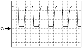
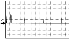
Inspection Using An Oscilloscope (Reference)
MAF sensor signal
am2zzw00006338
|
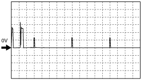
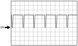
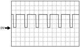
Fuel injector (high) signal
am2zzw00003096
|
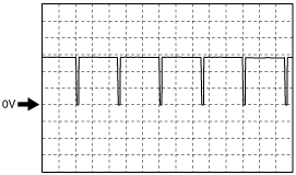
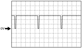
CMP sensor signal
am2zzw00002954
|
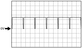
Intake shutter valve actuator (-) signal
am2zzw00006339
|
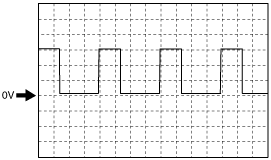
Fuel injector (low) signal
am2zzw00003097
|
EGR valve actuator (-) signal
am2zzw00006340
|
EGR valve actuator (+) signal
am2zzw00006341
|
Intake shutter valve actuator (+) signal
am2zzw00006342
|
Fuel metering valve control signal
am2zzw00006343
|
Wastegate valve actuator control solenoid valve signal
am2zzw00006344
|
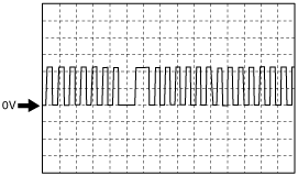
CKP sensor signal
am2zzw00006345
|
Using M-MDS
1. Connect the M-MDS to the DLC-2. (See ON-BOARD DIAGNOSTIC TEST [MZ-CD 1.6].)
2. Measure the PID value.
3. Switch the ignition to ON.
PID Monitor Table
|
Monitor item (Definition) |
Unit/Condition |
Condition/Specification (Reference) |
Inspection item |
||||||
|---|---|---|---|---|---|---|---|---|---|
|
AAT
(Ambient air temperature)
|
°C
|
°F
|
Indicates the ambient air temperature
|
—
|
|||||
|
AC_PRES
(Refrigerant pressure sensor)
|
Pa
|
Bar
|
psi
|
Idle
|
A/C switch ON: Approx. 1.15 MPa
A/C switch OFF: Approx. 807 kPa
|
• Refrigerant pressure sensor
|
|||
|
V
|
A/C switch ON: Approx. 1.83 V
A/C switch OFF: Approx.1.43 V
|
||||||||
|
AC_REQ
(A/C request signal)
|
On/Off
|
A/C switch ON: On
A/C switch OFF: Off
|
• A/C switch
|
||||||
|
ACCS
(Air conditioning compressor cycling switch)
|
On/Off
|
A/C switch ON: On
A/C switch OFF: Off
|
• The following PIDs
|
||||||
|
ALTF
(Generator field coil control duty signal)
|
%
|
Idle: Approx. 51%
|
• The following PIDs
• Generator
|
||||||
|
APP1
(Accelerator pedal position No.1)
|
%
|
Switch the ignition ON
|
Accelerator pedal released: 8.23 %
Accelerator pedal depressed: 65.88 %
|
• APP sensor
|
|||||
|
APP2
(Accelerator pedal position No.2)
|
%
|
Switch the ignition ON
|
Accelerator pedal released: 7.84 %
Accelerator pedal depressed: 66.05 %
|
• APP sensor
|
|||||
|
ARPMDES
(Target idle speed)
|
RPM
|
Indicates the target idle speed
|
—
|
||||||
|
BARO
(Barometric pressure)
|
Pa
|
Bar
|
psi
|
Indicates the atmospheric pressure
|
• PCM
|
||||
|
BAT
(Boost air temperature sensor)
|
°C
|
°F
|
Indicates the intake air temperature.
|
• Boost air temperature sensor
|
|||||
|
V
|
BAT 40 °C {104 °F}: Approx. 2.7 V
BAT 45 °C {113 °F}: Approx. 2.5 V
BAT 60 °C {140 °F}: Approx. 1.8 V
|
||||||||
|
BOO
(Brake switch)
|
On/Off
|
Brake pedal is depressed: On
Brake pedal is released: Off
|
• Brake switch
|
||||||
|
BPA
(Brake pressure applied switch)
|
On/Off
|
Brake pedal is depressed: On
Brake pedal is released: Off
|
• Brake switch
|
||||||
|
CATT11_DSD
(Exhaust gas temperature sensor No.1)
|
°C
|
°F
|
Indicates the target/estimated exhaust gas temperature. (Exhaust gas temperature sensor No.1)
|
• Exhaust gas temperature sensor No.1
|
|||||
|
CATT12_DSD
(Exhaust gas temperature sensor No.2)
|
°C
|
°F
|
Indicates the target/estimated exhaust gas temperature. (Exhaust gas temperature sensor No.2)
|
• Exhaust gas temperature sensor No.2
|
|||||
|
CRASH_ST
|
FLASE/TRUE
|
This item is displayed on the screen, however it does not function.
|
|||||||
|
ECT
(Engine coolant temperature)
|
V
|
ECT 30 °C {86 °F}: Approx. 2.6 V
ECT 50 °C {122 °F}: Approx. 1.7 V
ECT 70 °C {158 °F}: Approx. 1.1 V
|
• ECT sensor
|
||||||
|
°C
|
°F
|
Indicates the engine coolant temperature.
|
|||||||
|
EGR_C_BP
(EGR cooler bypass valve)
|
%
|
Idle: Approx. 98 %
|
• EGR cooler bypass valve
|
||||||
|
EGR_C_BP_D
(EGR cooler bypass valve position)
|
%
|
Idle: Approx. 98 %
|
• EGR cooler bypass valve position sensor
|
||||||
|
EGR_C_BP_P
(EGR cooler bypass valve position sensor)
|
V
|
Idle: Approx. 0 %
|
• EGR cooler bypass valve position sensor
|
||||||
|
%
|
Idle: Approx. 4.1 V
|
||||||||
|
EGRP
(EGR valve position)
|
V
|
Idle: Approx. 3.0 V
Switch the ignition ON: Approx. 2.58 V
|
• EGR valve
|
||||||
|
%
|
Indicates the EGR valve opening angle.
|
||||||||
|
EQ_RAT11
(Equivalence Ratio (Lambda))
|
—
|
Idle: Approx. 1.99
|
• The following PIDs
|
||||||
|
ETC_DSD
(Electronic throttle control desired)
|
%
|
Under any condition: 100 %
|
• Intake shutter valve
|
||||||
|
EXHPRESS_DIF
(Exhaust gas differential pressure)
|
Pa
|
Bar
|
psi
|
Indicates the difference in exhaust gas pressure before and after passing the diesel particulate filter.
|
• Diesel particulate filter differential pressure sensor
|
||||
|
V
|
Under any condition: 0.5 V
|
||||||||
|
EXHTEMP1
(Exhaust gas temperature sensor No.1)
|
V
|
Idle: Approx. 4.93 V
|
• Exhaust gas temperature sensor No.1
|
||||||
|
EXHTEMP2
(Exhaust gas temperature sensor No.2)
|
V
|
Idle: Approx. 4.99 V
|
• Exhaust gas temperature sensor No.2
|
||||||
|
FAN1
(FAN1 control signal)
|
On/Off
|
Cooling fan relay No.1 operating: ON
Cooling fan relay No.1 not operating: OFF
|
• Cooling fan relay No.1
|
||||||
|
FAN2
(FAN2 control signal)
|
On/Off
|
Cooling fan relay No.3 operating: ON
Cooling fan relay No.3 not operating: OFF
|
• Cooling fan relay No.3
|
||||||
|
FLT
(Fuel temperature)
|
°C
|
°F
|
Indicates the fuel temperature.
|
• Fuel temperature sensor
|
|||||
|
V
|
FLT 25 °C {77 °F}: Approx. 2.43 V
FLT 38 °C {100 °F}: Approx. 1.74 V
|
||||||||
|
FRP
(Fuel rail pressure)
|
V
|
Switch the ignition ON: Approx. 0.5 V
Idle: Approx. 1.0 V
Engine speed is 2,000 rpm: 1.6 V
|
• Fuel pressure sensor
|
||||||
|
Pa
|
Bar
|
psi
|
Idle: Approx. 22 MPa
Switch the ignition ON: Approx. 0 MPa
|
||||||
|
FRP_DSD
(Fuel rail pressure desired)
|
Pa
|
Bar
|
psi
|
Idle: Approx. 33 MPa
|
• Fuel pressure sensor
|
||||
|
FUEL_V_DSD
(Desired fuel volume)
|
mm3
|
Idle: Approx. 7 mm3
|
• Fuel metering valve
|
||||||
|
GPC
(Glow plug control module)
|
On/Off
|
Glow plug operating: On
Glow plug not operating: Off
|
• Glow plug control module
|
||||||
|
GPC_MON
(Glow plug control module monitor)
|
On/Off
|
Glow plug relay operating: On
Glow plug relay not operating: Off
|
• Glow plug control module
|
||||||
|
IAT
(Intake air temperature)
|
V
|
IAT 29 °C {84 °F}: Approx. 2.2 V
IAT 33 °C {91 °F}: Approx. 1.8 V
IAT 44 °C {111 °F}: Approx. 1.5 V
|
• IAT sensor
|
||||||
|
°C
|
°F
|
Indicates the intake air temperature.
|
|||||||
|
IG_SW
(Ignition switch)
|
On/Off
|
Indicates the ignition switch status.
|
• Ignition switch
|
||||||
|
LOAD
(Engine load)
|
%
|
Idle: Approx. 19 %
Switch the ignition ON: 0 %
|
—
|
||||||
|
LOW_OIL
(Engine oil)
|
Yes/No
|
Indicates the engine oil level status.
|
—
|
||||||
|
MAF
(Mass air flow)
|
g/sec
|
Idle: 6.8 g/sec
|
• MAF sensor
|
||||||
|
MAF_DSD
(Mass air flow desired)
|
g/sec
|
Idle: 0.11 g/sec
|
• MAF sensor
|
||||||
|
MAP
(Manifold absolute pressure sensor)
|
Pa
|
Bar
|
psi
|
Indicates the manifold absolute pressure.
|
• MAP sensor
|
||||
|
V
|
MAP 101 kPa: Approx. 1.56 V
|
||||||||
|
MIL_DIS
(The distance travelled since the MIL was activated.)
|
Km
|
mile
|
Indicates the travelled distance since the MIL illuminated.
|
—
|
|||||
|
O2S11
(A/F sensor)
|
V
|
Idle: Approx. 3 V
|
• A/F sensor
|
||||||
|
RPM
(Engine revolutions per minute)
|
RPM
|
Indicates the engine revolutions per minute.
|
• CKP sensor
|
||||||
|
SED_SW
(Sedimentor switch)
|
On/Off
|
Indicates the sedimentor switch.
|
• Sedimentor switch
|
||||||
|
SEGRP DSD
(Desired SEGRP valve position)
|
%
|
Indicates the desired EGR valve position.
|
• EGR valve
|
||||||
|
TP REL
(Relative throttle position)
|
%
|
Idle: Approx. 0 %
|
• Intake shutter valve
|
||||||
|
TP1
(Throttle position sensor)
|
V
|
Switch the ignition ON: Approx. 0.6 V
|
• Intake shutter valve
|
||||||
|
%
|
Idle: Approx. 87 %
|
||||||||
|
VPWR
(Module supply voltage)
|
V
|
Switch the ignition ON: B+
|
• Battery
• Main relay
|
||||||
|
VSS
(Vehicle speed)
|
KPH
|
Indicates the vehicle speed.
|
• Wheel-speed sensor
|
||||||
|
WG_POS
(Waste gate position sensor)
|
V
|
Idle: Approx. 3.0 V
|
• Wastegate valve actuator position sensor
|
||||||
|
WGC
(WGC solenoid valve)
|
%
|
Idle: Approx. 57 %
|
• Wastegate valve actuator control solenoid valve
|
||||||