 |
am2zzw00006168
DRIVE SHAFT (ATX, CVT) DISASSEMBLY/ASSEMBLY
id031300252400
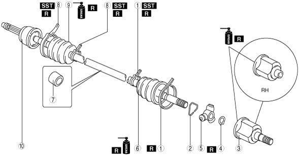
1. Disassemble in the order indicated in the table.
2. Assemble in the reverse order of disassembly.
am2zzw00006168
|
|
1
|
Boot band (transaxle side)
|
|
2
|
Clip
|
|
3
|
Outer ring
(See Outer Ring Assembly Note.)
|
|
4
|
Snap ring
|
|
5
|
Tripod joint
|
|
6
|
Boot
(See Boot Disassembly Note.)
(See Boot Assembly Note.)
|
|
7
|
Dynamic damper
|
|
8
|
Boot band (wheel side)
|
|
9
|
Boot
(See Boot Disassembly Note.)
(See Boot Assembly Note.)
|
|
10
|
Shaft and ball joint component
|
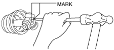
Clip, Outer Ring Disassembly Note
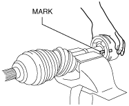
1. Mark the drive shaft and outer ring.
am2zzw00006169
|
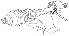
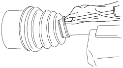
2. Remove the clip.
am2zzw00006170
|
3. Remove the outer ring.
Snap Ring And Tripod Joint Disassembly Note
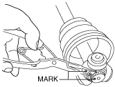
1. Mark the shaft and tripod joint.
2. Remove the snap ring using a snap ring pliers.
am2zzw00006171
|
3. Remove the tripod joint from the shaft.
Boot Disassembly Note
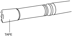
1. Wrap the shaft splines with tape.
am2zzw00006172
|
2. Remove the boot.
Boot Assembly Note
1. Fill the inside of the new dust boot (wheel side) with grease.
2. Install the boot with the splines of the shaft still wrapped in tape from disassembly.
3. Remove the tape.
Tripod Joint And Snap Ring Assembly Note
1. Align the marks and insert the tripod joint using a bar and a hammer.
am2zzw00006173
|
2. Insert a new snap ring using a snap ring pliers.
Outer Ring Assembly Note
1. Fill the outer ring and boot (transaxle side) with the specified grease.
2. Assemble the outer ring.
3. Set the drive shaft to the standard length.
4. Release any trapped air from the boots by carefully lifting up the small end of each boot with a cloth wrapped screwdriver.
avejjw00001218
|
5. Verify that the drive shaft length is within the standard under atmospheric pressure inside the boot.