 |
am2zzw00004967
PID/DATA MONITOR INSPECTION [FN4A-EL]
id050218805600
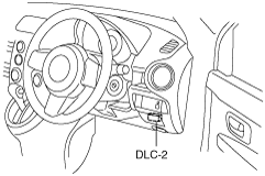
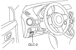
1. Connect the M-MDS (IDS) to the DLC-2.
L.H.D.
am2zzw00004967
|
R.H.D.
am2zzw00000606
|
2. After the vehicle is identified, select the following items from the initialization screen of the IDS.
3. Select the applicable PID from the PID table.
4. Measure the PID value.
PID/DATA MONITOR AND RECORD function table
|
Monitor item |
Unit/Condition |
Condition/Specification |
Action |
PCM terminal |
|
|---|---|---|---|---|---|
|
DGP_DIS_1
|
Km {mile}
|
This PID indicates the traveled distance since DTC P1712:00 was last recorded
|
—
|
N/A
|
|
|
DGP_DIS_2
|
Km {mile}
|
This PID indicates the traveled distance since the maximum rotation speed difference occurred between the left and right drive wheels
|
—
|
N/A
|
|
|
DGP_MAX_DIF
|
RPM
|
This PID indicates the maximum rotation speed difference between the left and right drive wheels
|
—
|
N/A
|
|
|
DGP_SPD
|
KPH {MPH}
|
This PID Indicates the vehicle speed with the trailing wheels at the time the maximum rotation speed difference between the left and right drive wheels occurred
|
—
|
N/A
|
|
|
GEAR
|
1st/2nd/3rd/4th
|
• 1GR: 1st
• 2GR: 2nd
• 3GR: 3rd
• 4GR: 4th
|
Inspect the following PIDs:
SSA/SS1, SSB/SS2, SSC/SS3, SSD/SS4, SSE_SS5
|
N/A
|
|
|
HTM_CNT
|
—
|
Indicates number of high oil temperature mode (ATF temperature at 130 °C {266 °F} or more) operations
|
—
|
N/A
|
|
|
HTM_DIS
|
km
|
mile
|
Indicates travel distance after operation of high oil temperature mode (ATF temperature at 130 °C {266 °F} or more)
|
—
|
N/A
|
|
LINEDES
|
Pa
|
kgf/cm2, psi
|
Idling at P position: approx. 400 kPa {4.08 kgf/cm2, 58.0 psi}
|
Inspect the following PIDs:
TFT, TFTV, TR, TR_SENS, TSS, VSS
|
N/A
|
|
LPS
|
A
|
Idling at P position: approx. 950 mA
|
Inspect the pressure control solenoid.
|
1P, 1T
|
|
|
OSS
|
RPM
|
• Vehicle speed 0 km/h {0 mph}: 0 RPM
• Vehicle speed 25 km/h {16 mph}: 200—230 RPM
|
Inspect the VSS.
|
1AX
|
|
|
SSA/SS1
|
%
|
• 4GR: approx. 99%
• Others: approx. 0%
|
Inspect the shift solenoid A.
|
1D
|
|
|
SSB/SS2
|
%
|
• Idling at D range: approx. 99%
• Others: approx. 0%
|
Inspect the shift solenoid B.
|
1H
|
|
|
SSC/SS3
|
%
|
• Idling at D range: approx. 99%
• Others: approx. 0%
|
Inspect the shift solenoid C.
|
1L
|
|
|
SSD/SS4
|
On/Off
|
• P, N position: On
• Others: Off
|
Inspect the shift solenoid D.
|
1K
|
|
|
SSE_SS5
|
On/Off
|
• HOLD mode at L range: On
• Others: Off
|
Inspect the shift solenoid E.
|
1O
|
|
|
TCS
|
On/Off
|
• HOLD switch released: Off
• HOLD switch depressed: On
|
Inspect the HOLD switch.
|
1N
|
|
|
TFT
|
°C
|
°F
|
• ATF 20 °C {68 °F}: approx. 20 °C {68 °F}
• ATF 40 °C {104 °F}: approx. 40 °C {104 °F}
• ATF 60 °C {140 °F}: approx. 60 °C {140 °F}
|
Inspect the TFT sensor.
|
1AH, 1AG
|
|
TFTV
|
V
|
• ATF 20 °C {68 °F}: approx. 3.3 V
• ATF 40 °C {104 °F}: approx. 2.4 V
• ATF 60 °C {140 °F}: approx. 1.5 V
|
Inspect the TFT sensor.
|
1AH, 1AG
|
|
|
TR
|
P/R/N/D/S/L
|
• P position: P
• R position: R
• N position: N
• D range: D
• S range: S
• L range: L
|
Inspect the TR switch.
|
1AS, 1AG
|
|
|
TR_SENS
|
V
|
• P position: approx. 4.6 V
• R position: approx. 3.9 V
• N position: approx. 3.3 V
• D range: approx. 2.5 V
• S range: approx. 1.7 V
• L range: approx. 0.9 V
|
Inspect the TR switch.
|
1AS, 1AG
|
|
|
TSS
|
RPM
|
• Idling: 700—800 RPM
|
Inspect the input/turbine speed sensor.
|
1R, 1V
|
|