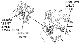
Caution
• Be sure to align the parking rod and the manual valve.
am2zzw00000822
|
CONTROL VALVE BODY INSTALLATION [FN4A-EL]
id051701806200
On-Vehicle Installation
am2zzw00000822
|
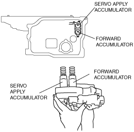
1. Install the accumulator springs and accumulators into the transaxle case.
am2zzw00000823
|
|
Spring |
Outer diameter (mm {in}) |
Free Length (mm {in}) |
No. of coils |
Wire diameter (mm {in}) |
|---|---|---|---|---|
|
Servo apply accumulator large spring
|
21.0
{0.827}
|
67.8
{2.669}
|
10.3
|
3.5
{0.138}
|
|
Servo apply accumulator small spring
|
13.0
{0.512}
|
67.8
{2.669}
|
17.1
|
2.2
{0.087}
|
|
Forward accumulator large spring
|
21.0
{0.827}
|
75.0
{2.953}
|
10.7
|
2.3
{0.091}
|
|
Forward accumulator small spring
|
15.6
{0.614}
|
49.0
{1.929}
|
7.7
|
2.4
{0.094}
|
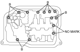
2. Install the control valve body component.
am2zzw00000824
|
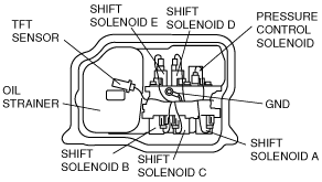
3. Install the oil strainer.
4. Match the harness colors, then connect the solenoid connector and TFT sensor.
|
Spring |
Color of connector (harness side) |
|---|---|
|
Pressure control solenoid
|
Black
|
|
Shift solenoid A
|
White
|
|
Shift solenoid B
|
Blue
|
|
Shift solenoid C
|
Green
|
|
Shift solenoid D
|
White
|
|
Shift solenoid E
|
Black
|
5. Install the ground.
am2zzw00000825
|
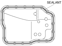
6. Apply a light coat of silicon sealant (TB1217E or equivalent) to the contact surfaces of the oil pan and transaxle case.
am2zzw00000826
|
7. Install the oil pan before the applied sealant starts to harden.
8. Add ATF. (See AUTOMATIC TRANSAXLE FLUID (ATF) REPLACEMENT [FN4A-EL].)
9. Connect the negative battery cable.
10. Perform the mechanical system test. (See MECHANICAL SYSTEM TEST [FN4A-EL].)