 |
am2zzw00006177
STEERING GEAR AND LINKAGE ASSEMBLY
id061300802100
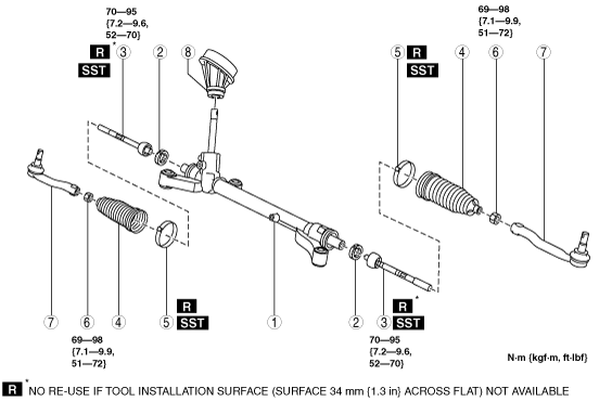
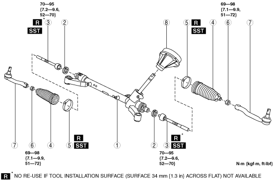
1. Assemble in the order shown in the figure.
L.H.D.
am2zzw00006177
|
R.H.D.
am2zzw00001394
|
|
1
|
Steering gear
|
|
2
|
Stopper
|
|
3
|
Tie rod
(See Tie Rod Assembly Note .)
|
|
4
|
Boot
|
|
5
|
Boot clamp
(See Boot Clamp Assembly Note .)
|
|
6
|
Locknut
|
|
7
|
Tie-rod end
(See Tie-rod End Assembly Note.)
|
|
8
|
Dust cover
|
Tie Rod Assembly Note
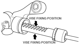
1. Protect the steering rack tooth surface using a clean cloth and secure it using a vise.
am2zzw00005880
|
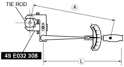
2. Combine the the SST with the torque wrench, then measure A and L as shown in the figure.
am2zzw00006926
|
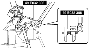
3. Recalculate the torque by using torque formulas, then tighten the tie rod using the SST.
adejjw00002409
|
Torque formula
|
Torque unit |
Formula |
|---|---|
|
N·m
|
N·m×[L/A]
|
|
kgf·m
|
kgf·m×[L/A]
|
|
ft·lbf
|
ft·lbf×[L/A]
|
Boot Clamp Assembly Note
1. Assemble the boot clamp to the steering gear.
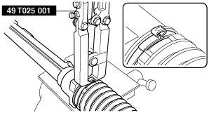
2. Crimp the boot clamp using the SST.
adejjw00002410
|
3. Rotate the by hand and verify that it is securely installed to the boot clamp.
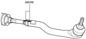
Tie-rod End Assembly Note
1. Align the alignment marks made before removal and assemble the tie-rod end to the tie rod.
am2zzw00001118
|
2. Adjust dimension A shown in the figure to the standard, then assemble the tie-rod end.
adejjw00002696
|