 |
am2zzw00005577
CLIMATE CONTROL UNIT INSPECTION [FULL-AUTO AIR CONDITIONER]
id0740a1802200
1. Remove the climate control unit with the connector connected. (See CLIMATE CONTROL UNIT REMOVAL/INSTALLATION [FULL-AUTO AIR CONDITIONER].)
2. Switch the ignition to ON.
3. Connect the negative (-) lead of the tester to the body ground.
4. Insert the positive (+) lead of the climate control unit connector and measure the voltage of each terminal following the terminal voltage table.
Terminal Voltage Table (Reference)
am2zzw00005577
|
|
Terminal |
Signal name |
Connected to |
Measurement condition |
Voltage (V) |
Inspection item(s) |
|---|---|---|---|---|---|
|
A
|
Motor operation
(FRESH)
|
Air intake actuator
|
Switched to RECIRCULATE
|
1.0 or less
|
• Air intake actuator
• Related wiring harness
|
|
Switched to FRESH
|
12
|
||||
|
B
|
Ground
|
Body ground
|
Under any condition
|
1.0 or less
|
• Related wiring harness
|
|
C
|
IG2
|
• Ignition switch
• A/C 7.5 A fuse
|
Ignition switch is at ON position
|
B+
|
• Ignition switch
• A/C 7.5 A fuse
• Related wiring harness
|
|
Ignition switch is at LOCK position
|
1.0 or less
|
||||
|
D
|
Motor operation
(REC)
|
Air intake actuator
|
Switched to RECIRCULATE
|
12
|
• Air intake actuator
• Related wiring harness
|
|
Switched to FRESH
|
1.0 or less
|
||||
|
E
|
B+
|
• ROOM 15 A fuse*1
• BCM*2
|
Under any condition
|
B+
|
• ROOM 15 A fuse*1
• BCM*2
• Related wiring harness
|
|
F
|
Motor operation
(VENT)
|
Airflow mode actuator
|
Switched to DEFROSTER
|
1.0 or less
|
• Airflow mode actuator
• Related wiring harness
|
|
Switched to VENT
|
12
|
||||
|
G
|
Motor operation
HOT
|
Air mix actuator
|
Switched to COLD
|
1.0 or less
|
• Air mix actuator
• Related wiring harness
|
|
Switched to HOT
|
12
|
||||
|
H
|
Motor operation
(DEFROSTER)
|
Airflow mode actuator
|
Switched to DEFROSTER
|
12
|
• Airflow mode actuator
• Related wiring harness
|
|
Switched to VENT
|
1.0 or less
|
||||
|
I
|
TNS
|
TNS relay (BCM)
|
Light switch off
|
1.0 or less
|
• Light switch
• TNS relay
• BCM
• Related wiring harness
|
|
Light switch on
(TNS, headlights)
|
B+
|
||||
|
J
|
Motor operation
COLD
|
Air mix actuator
|
Switched to COLD
|
12
|
• Air mix actuator
• Related wiring harness
|
|
Switched to HOT
|
1.0 or less
|
||||
|
K
|
Potentiometer input
|
Airflow mode actuator
|
VENT
|
4.3
|
• Airflow mode actuator
• Related wiring harness
|
|
BI-LEVEL
|
3.5
|
||||
|
HEAT
|
2.6
|
||||
|
HEAT/DEF
|
1.6
|
||||
|
DEFROSTER
|
0.6
|
||||
|
L
|
Panel light control input
|
Instrument cluster
|
Headlight ON and panel light control MAX
|
2.0
|
• Instrument cluster
• Related wiring harness
|
|
Headlight ON and panel light control MIN
|
10.2
|
||||
|
M
|
Potentiometer input
|
Air mix actuator
|
Set temperature at MAX COLD
|
0.7
|
• Air mix actuator
• Related wiring harness
|
|
Set temperature at MAX HOT
|
4.3
|
||||
|
N
|
Rear window defroster indicator output
|
BCM
|
Rear window defroster on
|
1.0 or less
|
• BCM
• Related wiring harness
|
|
Rear window defroster off
|
9.8
|
||||
|
O*4
|
PTC request
|
Instrument cluster
|
PTC heater operation
|
1.0 or less
|
• Instrument cluster
• Related wiring harness
|
|
PTC heater stopped
|
5.0
|
||||
|
O*5
|
Fan speed output
|
Instrument cluster
|
Fan speed high (4th or more)
|
1.0 or less
|
• Instrument cluster
• Related wiring harness
|
|
Fan speed low (3rd or less)
|
5.0
|
||||
|
P
|
Solar radiation signal input
|
Solar radiation sensor
|
Light shone on solar radiation sensor
|
Detects voltage value
|
• Solar radiation sensor
• Related wiring harness
|
|
Light blocked to solar radiation sensor
|
0
|
||||
|
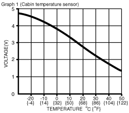
Q
|
Cabin temperature signal input
|
Cabin temperature sensor
|
Compared with temperature detected by cabin temperature sensor
|
Refer to graph 1
|
• Cabin temperature sensor
• Related wiring harness
|
|
R*3
|
A/C
|
• Refrigerant pressure switch
• PCM
|
Fan stopped
|
5.0
|
• Refrigerant pressure switch
• PCM
• Related wiring harness
|
|
Fan switch on and A/C switch on
|
2.6
|
||||
|
R*4
|
A/C
|
Instrument cluster
|
Fan stopped
|
5.0
|
• Instrument cluster
• Related wiring harness
|
|
Fan switch on and A/C switch on
|
1.0 or less
|
||||
|
S
|
Sensor ground
|
• Cabin temperature sensor
• Air mix actuator
• Airflow mode actuator
|
Under any condition
|
1.0 or less
|
• Related wiring harness
|
|
T
|
Serial Communication
|
Instrument cluster
|
Because this terminal is for communication, good/no good judgment by terminal voltage is not possible.
|
• Instrument cluster
• Related wiring harness
|
|
|
U
|
Blower fan speed control
|
Power MOS FET
|
Fan stopped
|
1.0 or less
|
• Power MOS FET
• Related wiring harness
|
|
Fan: manual LO (1)
|
2.9
|
||||
|
Fan: manual HI (7)
|
10.3
|
||||
|
V
|
Rear window defroster operation
|
BCM
|
Rear window defroster switch off
|
1.8
|
• BCM
• Related wiring harness
|
|
Rear window defroster switch on
|
1.0 or less
|
||||
|
W
|
Blower motor feedback
|
• Blower motor
• Power MOS FET
|
Fan stopped
|
B+
|
1. Related wiring harness
2. Power MOS FET
3. Blower motor
4. Blower relay
5. A/C 7.5 A fuse
6. BLOWER 30 A fuse
7. Replace power MOS FET
|
|
Fan: manual LO (1)
|
9.5
|
||||
|
Fan: manual HI (7)
|
0.4
|
||||
|
X
|
5 V
|
• Air mix actuator
• Airflow mode actuator
• Solar radiation sensor
|
Ignition switch is at ON position
|
5.0
|
• Air mix actuator
• Airflow mode actuator
• Solar radiation sensor
• Related wiring harness
|
|
Ignition switch is at LOCK position
|
1.0 or less
|
||||
|
Y
|
―
|
―
|
―
|
―
|
―
|
|
Z
|
―
|
―
|
―
|
―
|
―
|
 |
―
|