 |
am2zzw00006019
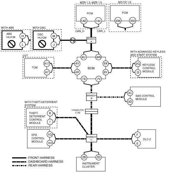
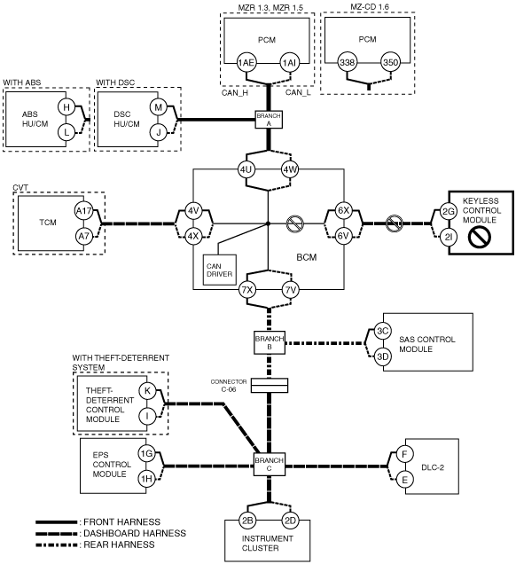
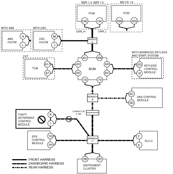
DETERMINING MALFUNCTIONING PART (HS-CAN) [MULTIPLEX COMMUNICATION SYSTEM (R.H.D.)]
id0902j4846700
1. Verify the CAN system-related module DTCs and the failed module using the (M-MDS).
2. Look for a DTC display pattern and failed module display pattern in tandem which match.
3. Refer to the matching tandem diagnostic results (A to L) and inspect the possible cause and inspection item.
4. Perform the DTC inspection after the repair procedure.
Diagnostic Table for Determining Malfunctioning Part
|
M-MDS display |
DTC display pattern |
||||||||||||
|---|---|---|---|---|---|---|---|---|---|---|---|---|---|
|
DTC output module |
DTC |
||||||||||||
|
PCM (PCM)*1
|
U0121:00
|
|
×
|
|
|
|
|
|
|
|
|
|
|
|
U0140:00
|
|
|
|
|
×
|
|
|
|
|
|
|
|
|
|
U0151:00
|
|
|
|
|
|
|
|
×
|
|
|
|
|
|
|
U0155:00
|
|
|
|
|
|
|
|
|
|
|
|
×
|
|
|
PCM (PCM)*2
|
U0121:00
|
|
×
|
|
|
|
|
|
|
|
|
|
|
|
U0122:87
|
|
×
|
|
|
|
|
|
|
|
|
|
|
|
|
U0155:00
|
|
|
|
|
|
|
|
|
|
|
|
×
|
|
|
U0167:00
|
|
|
|
|
|
|
|
|
|
|
|
×
|
|
|
U0167:01
|
|
|
|
|
|
|
|
|
|
|
|
×
|
|
|
U0415:00
|
|
-
|
|
|
|
|
|
|
|
|
|
|
|
|
U0426:86
|
|
|
|
|
|
|
|
|
|
|
|
-
|
|
|
U0426:87
|
|
|
|
|
|
|
|
|
|
|
|
-
|
|
|
ABS (ABS HU/CM)*3
|
U0100:00
|
×
|
|
|
|
|
|
|
|
|
|
|
|
|
U0155:00
|
|
|
|
|
|
|
|
|
|
|
|
×
|
|
|
U2101:00
|
|
|
|
|
|
|
|
|
|
|
|
-
|
|
|
ABS (DSC HU/CM)*4
|
U0100:00
|
×
|
|
|
|
|
|
|
|
|
|
|
|
|
U0126:00
|
|
|
|
|
|
|
|
|
|
|
×
|
|
|
|
U0155:00
|
|
|
|
|
|
|
|
|
|
|
|
×
|
|
|
U0401:68
|
-
|
|
|
|
|
|
|
|
|
|
|
|
|
|
U2101:00
|
|
|
|
|
|
|
|
|
|
|
|
-
|
|
|
TCM (TCM)*5
|
U0100:00
|
×
|
|
×
|
|
|
|
|
|
|
|
|
|
|
U0121:00
|
|
×
|
×
|
|
|
|
|
|
|
|
|
|
|
|
BCM/GEM (BCM)
|
U0100:00
|
×
|
|
×
|
|
|
|
|
|
|
|
|
|
|
U0101:00
|
|
|
|
×
|
|
|
|
|
|
|
|
|
|
|
U0121:00
|
|
×
|
×
|
|
|
|
|
|
|
|
|
|
|
|
U0415:68
|
|
-
|
-
|
|
|
|
|
|
|
|
|
|
|
|
RKE (Keyless control module)*6
|
U0028:87
|
|
|
|
|
×
|
|
|
|
|
|
|
|
|
U0100:00
|
×
|
|
×
|
|
|
|
|
|
|
|
|
|
|
|
U0401:68
|
-
|
|
-
|
|
|
|
|
|
|
|
|
|
|
|
RCM (SAS control module)
|
U0155:00
|
|
|
|
|
|
|
|
|
|
|
|
×
|
|
VSM*7 (Theft-deterrent control module)
|
U0100:00
|
×
|
|
×
|
|
|
|
×
|
|
×
|
|
|
|
|
U0155:00
|
|
|
|
|
|
|
|
|
|
|
|
×
|
|
|
EPS (EPS control module)
|
U0100:00
|
×
|
|
×
|
|
|
|
×
|
|
×
|
|
|
|
|
U0401:00
|
|
|
|
|
|
|
|
|
|
|
|
|
|
|
IC (Instrument cluster)
|
U0100:00
|
×
|
|
×
|
|
|
|
×
|
|
×
|
|
|
|
|
U0101:00
|
|
|
|
×
|
|
|
×
|
|
×
|
|
|
|
|
|
U0121:00
|
|
×
|
×
|
|
|
|
×
|
|
×
|
|
|
|
|
|
U0131:00
|
|
|
|
|
|
|
|
|
|
|
×
|
|
|
|
U0140:00
|
|
|
|
|
×
|
|
×
|
|
×
|
|
|
|
|
|
U0151:00
|
|
|
|
|
|
|
|
×
|
×
|
|
|
|
|
|
U0214:00
|
|
|
|
|
|
×
|
×
|
|
×
|
|
|
|
|
|
U0401:68
|
-
|
|
-
|
|
|
|
-
|
|
-
|
|
|
|
|
|
U0401:92
|
-
|
|
-
|
|
|
|
-
|
|
-
|
|
|
|
|
|
U0402:68
|
|
|
|
-
|
|
|
-
|
|
-
|
|
|
|
|
|
U0402:92
|
|
|
|
-
|
|
|
-
|
|
-
|
|
|
|
|
|
U0415:92
|
|
-
|
-
|
|
|
|
-
|
|
-
|
|
|
|
|
|
U0420:92
|
|
|
|
|
|
|
|
|
|
|
-
|
|
|
|
U0452:68
|
|
|
|
|
|
|
|
-
|
-
|
|
|
|
|
|
U0452:92
|
|
|
|
|
|
|
|
-
|
-
|
|
|
|
|
|
U0515:68
|
|
|
|
|
|
-
|
-
|
|
-
|
|
|
|
|
|
U0515:92
|
|
|
|
|
|
-
|
-
|
|
-
|
|
|
|
|
|
U2005:86
|
-
|
|
-
|
|
|
|
-
|
|
-
|
|
|
|
|
|
M-MDS display module
|
“Fail” display pattern
|
||||||||||||
|
PCM
|
×
|
|
×
|
|
|
|
×
|
|
×
|
|
|
|
|
|
ABS
|
|
×
|
×
|
|
|
|
×
|
|
×
|
|
|
|
|
|
TCM*5
|
|
|
|
×
|
|
|
×
|
|
×
|
|
|
|
|
|
BCM/GEM
|
|
|
|
|
×
|
|
×
|
|
×
|
|
|
|
|
|
RKE*6
|
|
|
|
|
|
×
|
×
|
|
×
|
|
|
|
|
|
RCM
|
|
|
|
|
|
|
|
×
|
×
|
|
|
|
|
|
VSM*7
|
|
|
|
|
|
|
|
|
|
×
|
|
|
|
|
EPS
|
|
|
|
|
|
|
|
|
|
|
×
|
|
|
|
IC
|
|
|
|
|
|
|
|
|
|
|
|
×
|
|
|
Item
|
Diagnostic result
|
||||||||||||
|
Possible cause and inspection item
|
A
|
B
|
C
|
D
|
E
|
F
|
G
|
H
|
I
|
J
|
K
|
L
|
|
|
Reference page
|
|||||||||||||
A
Possible cause
System wiring diagram
am2zzw00006019
|
Inspection item
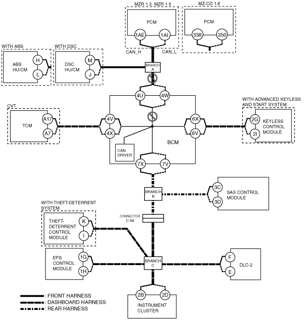
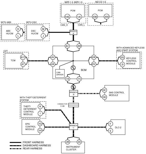
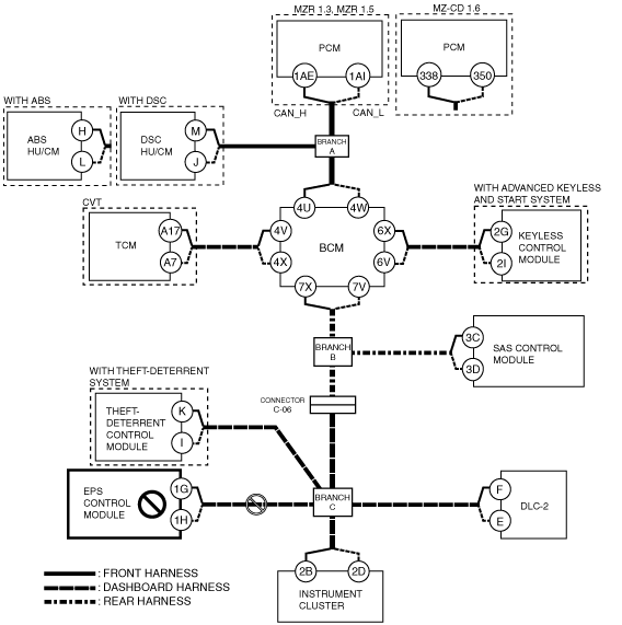
B
Possible cause
System wiring diagram
am2zzw00006020
|
Inspection item
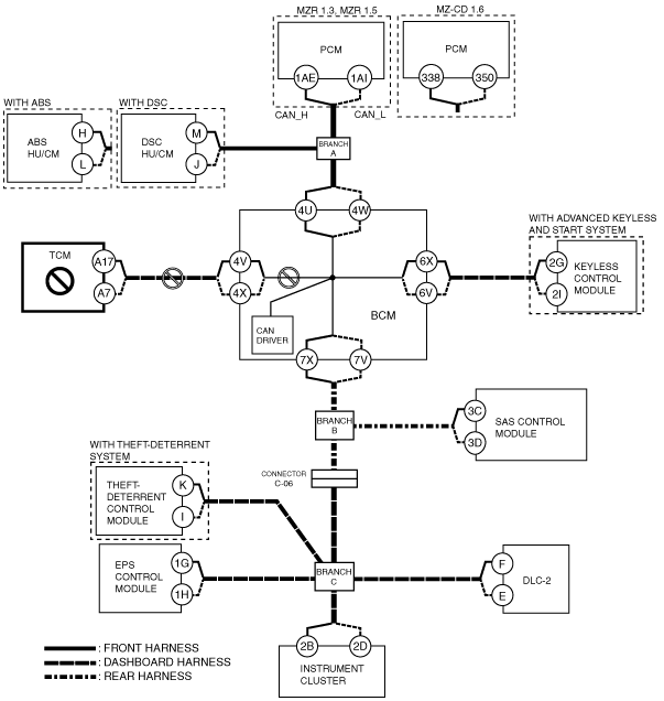
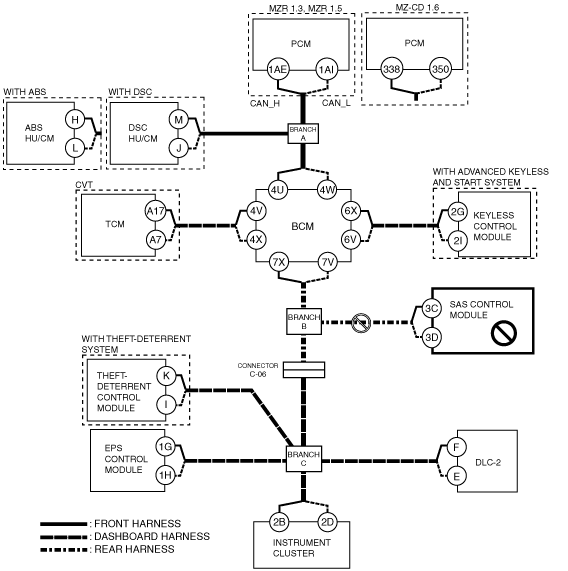
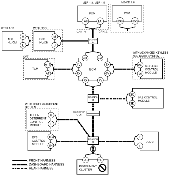
C
Possible cause
System wiring diagram
am2zzw00006022
|
Inspection item
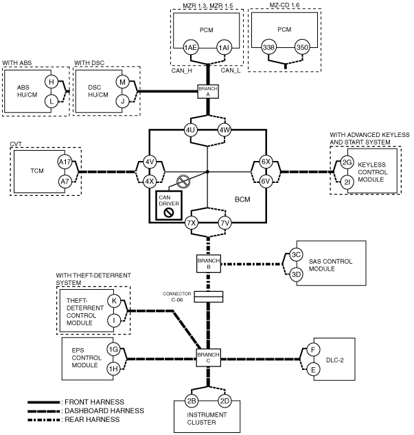
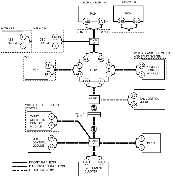
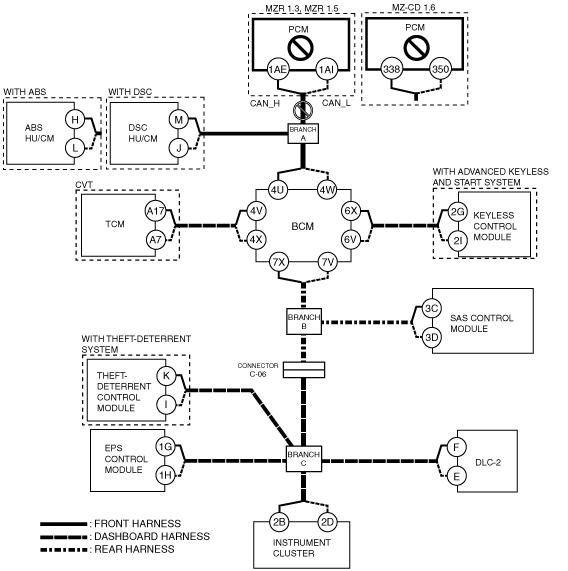
D
Possible cause
System wiring diagram
am2zzw00006023
|
Inspection item
E
Possible cause
System wiring diagram
am2zzw00006024
|
Inspection item
F
Possible cause
System wiring diagram
am2zzw00006025
|
Inspection item
G
Possible cause
System wiring diagram
am2zzw00006026
|
Inspection item
H
Possible cause
System wiring diagram
am2zzw00006027
|
Inspection item
I
Possible cause
System wiring diagram
am2zzw00006028
|
Inspection item
J
Possible cause
System wiring diagram
am2zzw00006029
|
Inspection item
K
Possible cause
System wiring diagram
am2zzw00006030
|
Inspection item
L
Possible cause
System wiring diagram
am2zzw00006031
|
Inspection item