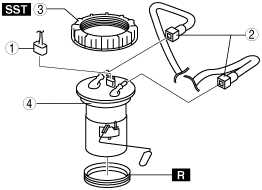
FUEL GAUGE SENDER UNIT REMOVAL/INSTALLATION


id092200497000


MZR 1.3, MZR 1.5

Note
•  The fuel gauge sender unit is integrated with the fuel pump unit

1.  Remove the fuel gauge sender unit. (See FUEL PUMP UNIT DISASSEMBLY/ASSEMBLY [MZR 1.3, MZR 1.5].)


MZ-CD 1.6

Warning
•  Fuel is very flammable liquid. If fuel spills or leaks from the pressurized fuel system, it will cause serious injury or death and facility breakage. Fuel can also irritate skin and eyes. To prevent this, always complete the “Fuel Line Safety Procedure”, while referring to “BEFORE SERVICE PRECAUTION”.
•  A person charged with static electricity could cause a fire or explosion, resulting in death or serious injury. Before draining fuel, make sure to discharge static electricity by touching the vehicle body.

1.  Complete the “BEFORE SERVICE PRECAUTION”. (See BEFORE SERVICE PRECAUTION [MZ-CD 1.6].)

2.  Disconnect the negative battery cable.

3.  Remove the rear seat cushion. (See REAR SEAT CUSHION REMOVAL/INSTALLATION.)

4.  Remove the service hole cover.

5.  Remove in the order indicated in the table.

am2zzw00002644

1
Fuel gauge sender unit connector
2
Quick release connector
3
Fuel gauge cap
4
Fuel gauge sender unit

6.  Install in the reverse order of removal.

7.  Complete the “AFTER SERVICE PRECAUTION”. (See AFTER SERVICE PRECAUTION [MZ-CD 1.6].)


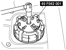
Fuel Gauge Cap Removal Note

Caution
•  The fuel gauge cap could be damaged if the SST is used with any gap between the cap and the SST. Securely attach the SST so that there is no gap between the SST tabs and the side of the cap.

1.  Remove the fuel gauge cap using the SST.

adejjw00001945


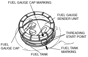
Fuel Gauge Cap Installation Note

Note
•  The fuel gauge sender unit will rotate and cannot be secured in the specified position if there is any gasoline on the gasket. Thoroughly wipe away all gasoline from the gasket.
•  Make the markings to be easily visible when the fuel gauge cap is installed.
•  Marks are provided on the fuel gauge sender unit and fuel tank for correct installation of the fuel gauge sender unit.

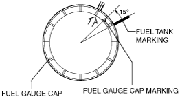
1.  Mark the fuel gauge cap and the fuel tank at the point where the threading of each part begins as shown in the figure.

am2zzw00002638

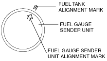
2.  Align the fuel tank alignment mark with the fuel gauge sender unit as shown in the figure.

am2zzw00002645

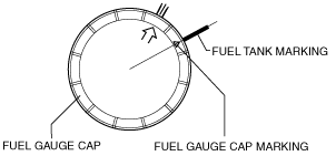
3.  Align the fuel tank and fuel gauge cap markings.

am2zzw00002646

4.  Rotate the fuel gauge cap counterclockwise until the cap marking is approx. 15° away from the fuel tank marking as shown in the figure.

am2zzw00002647

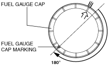
5.  While keeping the fuel gauge sender unit from rising up, tighten the fuel gauge cap by hand 180 ° clockwise.

am2zzw00002648

Caution
•  The cap could be damaged if the SST is used with any play between the cap and the SST. Securely install the SST so that there is no gap between the SST tabs and the side of the cap.

6.  Set the SST as shown in the figure.

adejjw00001945

Note
•  The total rotation angle is 450—495 °if the approx.180° from Step 5 is included.

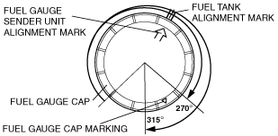
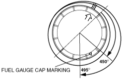
7.  Using the SST, tighten the fuel gauge cap within the specified rotation angle and cap tightening torque without shifting the fuel tank and fuel gauge sender unit alignment marks.

am2zzw00002649

Rotation angle
270—315°
Fuel gauge cap tightening torque
80—90 N·m {8.2—9.1 kgf·m, 59—66 ft·lbf}
Note
•  The total rotation angle is 450—495 ° if the approx.180 ° from Step 5 is included.
am2zzw00002650
•  If the specified tightening torque cannot be obtained, replace the fuel gauge cap and gasket.
•  If the specified tightening torque cannot be obtained after replacement of the fuel gauge cap and gasket, replace the fuel tank.