|
am2uun00000092
ON-BOARD DIAGNOSTIC FUNCTION [CAN (CONTROLLER AREA NETWORK)]
id094000104100
On-Board Diagnostic Function
Malfunction detection function
Fail-safe function
Memory function
Self-malfunction diagnostic function
HS-CAN
|
DTC output module (M-MDS display) |
DTC |
Malfunction location |
|---|---|---|
|
PCM (MZR 1.3, MZR 1.5)
(PCM)
|
U0073:00
|
CAN system communication error
|
|
U0121:00
|
• Communication error to ABS HU/CM (with ABS)
• Communication error to DSC HU/CM (with DSC)
|
|
|
U0140:00
|
Communication error to BCM
|
|
|
U0151:00
|
Communication error to SAS control module
|
|
|
U0155:00
|
Communication error to instrument cluster
|
|
|
PCM (MZ-CD 1.6)
(PCM)
|
U0001:00
|
CAN system communication error
|
|
U0073:00
|
CAN system communication error
|
|
|
U0121:00
|
• Communication error to ABS HU/CM (with ABS)
• Communication error to DSC HU/CM (with DSC)
|
|
|
U0122:86
|
||
|
U0122:87
|
||
|
U0155:00
|
Communication error to instrument cluster
|
|
|
U0167:00
|
||
|
U0121:00
|
• Communication error to keyless control module (vehicles with advanced keyless and start system)
• Communication error to instrument cluster (vehicles with keyless entry system)
|
|
|
ABS HU/CM*1
(ABS)
|
U0001:88
|
CAN system communication error
|
|
U0100:00
|
Communication error to PCM
|
|
|
U0155:00
|
Communication error to instrument cluster
|
|
|
U2101:00
|
Signal error from instrument cluster
|
|
|
DSC HU/CM*2
(ABS)
|
U0001:88
|
CAN system communication error
|
|
U0100:00
|
Communication error to PCM
|
|
|
U0126:00
|
Communication error to EPS control module
|
|
|
U0155:00
|
Communication error to instrument cluster
|
|
|
U0401:68
|
Signal error from PCM
|
|
|
U2101:00
|
Signal error from instrument cluster
|
|
|
SAS control module
(RCM)
|
U0001:88
|
CAN system communication error
|
|
U0155:00
|
Communication error to instrument cluster
|
|
|
BCM
(BCM/GEM)
|
U0001:88
|
CAN system communication error
|
|
U0100:00
|
Communication error to PCM
|
|
|
U0101:00
|
Communication error to TCM
|
|
|
U0121:00
|
• Communication error to ABS HU/CM (with ABS)
• Communication error to DSC HU/CM (with DSC)
|
|
|
U0415:68
|
• Signal error from ABS HU/CM (with ABS)
• Signal error from DSC HU/CM (with DSC)
|
|
|
TCM*3
(TCM)
|
U0073:00
|
CAN system communication error
|
|
U0100:00
|
Communication error to PCM
|
|
|
U0121:00
|
• Communication error to ABS HU/CM (with ABS)
• Communication error to DSC HU/CM (with DSC)
|
|
|
Keyless control module*4
(RKE)
|
U0001:88
|
CAN system communication error
|
|
U0028:87
|
Communication error to BCM
|
|
|
U0100:00
|
Communication error to PCM
|
|
|
U0401:68
|
Signal error from PCM
|
|
|
EPS control module
(EPS)
|
U0001:88
|
CAN system communication error
|
|
U0100:00
|
Communication error to PCM
|
|
|
U0401:00
|
Signal error from PCM
|
|
|
Theft-deterrent control module*5
(VSM)
|
U0001:88
|
CAN system communication error
|
|
U0100:00
|
Communication error to PCM
|
|
|
U0155:00
|
Communication error to instrument cluster
|
|
|
Instrument cluster
(IC)
|
U0001:88
|
CAN system communication error
|
|
U0100:00
|
Communication error to PCM
|
|
|
U0101:00
|
Communication error to TCM
|
|
|
U0121:00
|
• Communication error to ABS HU/CM (with ABS)
• Communication error to DSC HU/CM (with DSC)
|
|
|
U0131:00
|
Communication error to EPS control module
|
|
|
U0140:00
|
Communication error to BCM
|
|
|
U0151:00
|
Communication error to SAS control module
|
|
|
U0214:00
|
Communication error to keyless control module
|
|
|
U0401:68
|
Signal error from PCM
|
|
|
U0401:92
|
Signal error from PCM
|
|
|
U0402:68
|
Signal error from TCM
|
|
|
U0402:92
|
Signal error from TCM
|
|
|
U0415:92
|
• Signal error from ABS HU/CM (with ABS)
• Signal error from DSC HU/CM (with DSC)
|
|
|
U0420:92
|
Signal error from EPS control module
|
|
|
U0452:68
|
Signal error from SAS control module
|
|
|
U0452:92
|
Signal error from SAS control module
|
|
|
U0515:68
|
Signal error from keyless control module
|
|
|
U0515:92
|
Signal error from keyless control module
|
|
|
U2005:86
|
Signal error from PCM
|
Narrowing down malfunction locations
Troubleshooting procedure
am2uun00000092
|
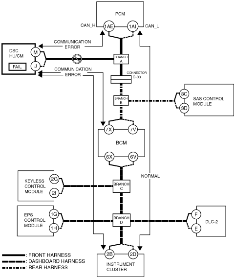
Example (L.H.D.): DSC HU/CM-related wiring harness open circuit (if DTC is output)
1. Verify the CAN system-related module DTCs and the failed module using the Mazda Modular Diagnostic System (M-MDS).
|
Module |
Displayed DTC |
Probable malfunction location |
|---|---|---|
|
PCM (PCM)
|
U0121:00
|
Communication error to DSC HU/CM
|
|
BCM (BCM/GEM)
|
U0121:00
|
Communication error to DSC HU/CM
|
|
IC (Instrument cluster)
|
U0121:00
|
Communication error to DSC HU/CM
|
|
Module |
Fail |
|---|---|
|
ABS (DSC HU/CM)
|
×
|
am2zzn00001508
|
2. Despite normal communication between the PCM and instrument cluster, a communication error DTC is displayed for the signal between the DSC HU/CM and PCM / BCM / instrument cluster. In addition, the wiring harness between the DSC HU/CM and branch A is considered to be malfunctioning because “Fail” is displayed for the DSC HU/CM.
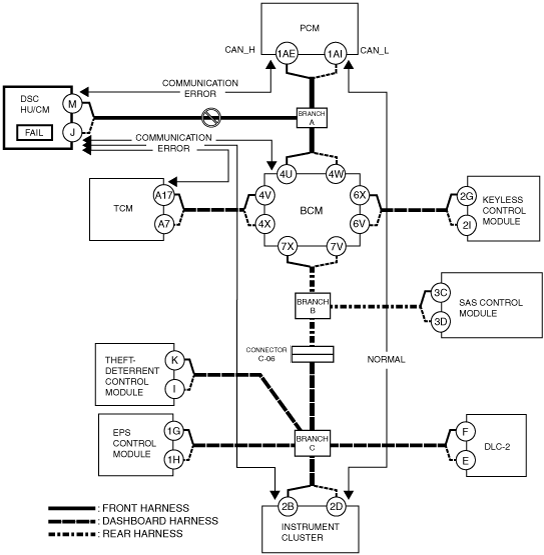
Example (R.H.D.): DSC HU/CM-related wiring harness open circuit (if DTC is output)
1. Verify the CAN system-related module DTCs and the failed module using the Mazda Modular Diagnostic System (M-MDS).
|
Module |
Displayed DTC |
Probable malfunction location |
|---|---|---|
|
PCM (PCM)
|
U0121:00
|
Communication error to DSC HU/CM
|
|
BCM (BCM/GEM)
|
U0121:00
|
Communication error to DSC HU/CM
|
|
TCM (TCM)
|
U0121:00
|
Communication error to DSC HU/CM
|
|
IC (Instrument cluster)
|
U0121:00
|
Communication error to DSC HU/CM
|
|
Module |
Fail |
|---|---|
|
ABS (DSC HU/CM)
|
×
|
am2zzn00001509
|
2. Despite normal communication between the PCM and instrument cluster, a communication error DTC is displayed for the signal between the DSC HU/CM and PCM / BCM / TCM / instrument cluster. In addition, the wiring harness between the DSC HU/CM and branch A is considered to be malfunctioning because “Fail” is displayed for the DSC HU/CM.