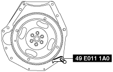
49 E011 1A0
Ring gear brake set
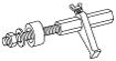
49 G028 205
Oil seal installer

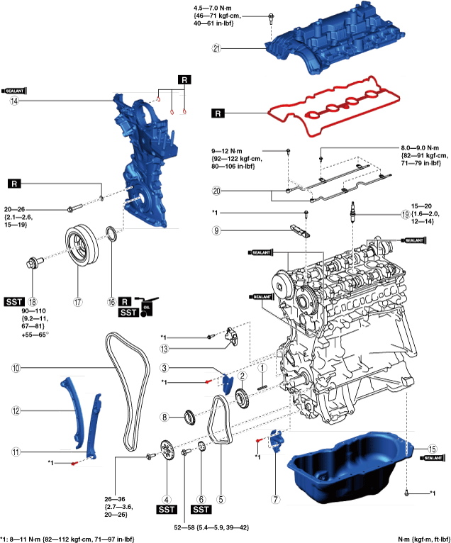
TIMING CHAIN ASSEMBLY
id011000505600
Special Service Tool (SST)
|
49 E011 1A0
Ring gear brake set
|
|
49 G028 205
Oil seal installer
|
|
Replacement Part
|
O-ring
Quantity: 3
Location of use: Engine front cover
|
Washer
Quantity: 1
Location of use: Engine front cover
|
Front oil seal
Quantity: 1
Location of use: Engine front cover
|
|
Cylinder head cover gasket
Quantity: 1
Location of use: Cylinder head cover
|
—
|
—
|
Oil and Chemical Type
|
Engine oil
Type: Recommended oil
|
Silicone sealant
Type: TB1217D or equivalent
|
am3uuw00008968
|
bpe7ze00000032
|
1. Assemble in the order indicated in the table.
btstze00000029
|
|
1
|
Key
|
|
2
|
Oil pump drive sprocket
|
|
3
|
Oil pump chain guide
|
|
4
|
Oil pump driven sprocket
(See Oil Pump Chain Assembly Note.)
|
|
5
|
Oil pump chain
(See Oil Pump Chain Assembly Note.)
|
|
6
|
Balancer shaft sprocket
(See Oil Pump Chain Assembly Note.)
|
|
7
|
Oil pump chain tensioner
(See Oil Pump Chain Assembly Note.)
|
|
8
|
Crankshaft sprocket
|
|
9
|
Chain guide (No.2)
|
|
10
|
Timing chain
(See Timing Chain Assembly Note.)
|
|
11
|
Chain guide (No.1)
(See Timing Chain Assembly Note.)
|
|
12
|
Tensioner arm
(See Timing Chain Assembly Note.)
|
|
13
|
Chain tensioner
(See Timing Chain Assembly Note.)
|
|
14
|
Engine front cover
|
|
15
|
Oil pan
(See Oil Pan Assembly Note.)
|
|
16
|
Front oil seal
(See Front Oil Seal Assembly Note.)
|
|
17
|
Crankshaft pulley
|
|
18
|
Crankshaft pulley lock bolt
|
|
19
|
Spark plug
|
|
20
|
Oil shower pipe
|
|
21
|
Cylinder head cover
|
Oil Pump Chain Assembly Note
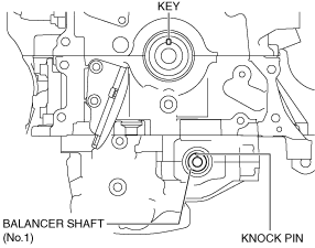
1. Verify that the key and knock pin are aligned to the positions shown in the figure.
ac5wzw00010915
|
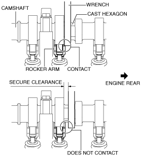
2. Temporarily assemble the oil pump driven sprocket.
3. Temporarily tighten the oil pump driven sprocket installation bolt.
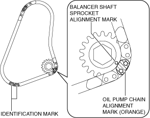
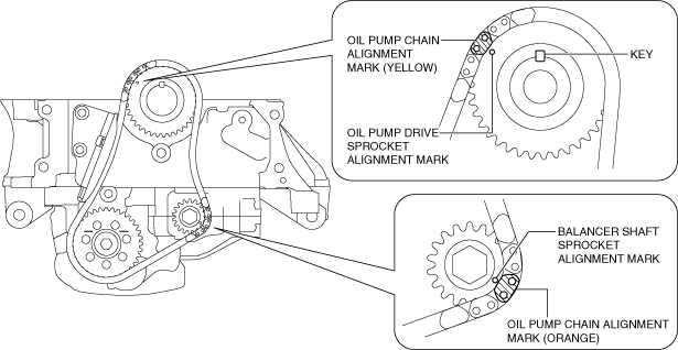
4. Align the oil pump chain alignment mark with the balancer shaft sprocket alignment mark.
btstze00000030
|
5. Install the oil pump chain and balancer shaft sprocket as a single unit while aligning the alignment marks on each sprocket and oil pump chain as shown in the figure.
btstze00000031
|
6. Temporarily tighten the balancer shaft sprocket installation bolt.
7. Install the oil pump chain tensioner.
8. Hold the crankshaft using the SST.
bpe1ze00000096
|
9. Tighten the oil pump driven sprocket installation bolt.
10. Tighten the balancer shaft sprocket installation bolt.
11. Remove the wire or paper clip installed to the oil pump chain tensioner and apply tension to the oil pump chain.
Timing Chain Assembly Note
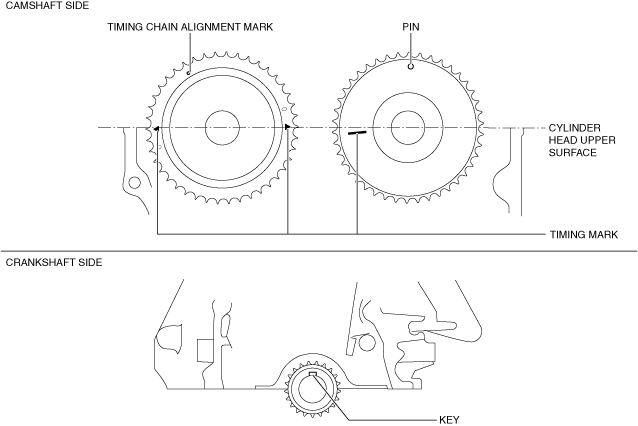
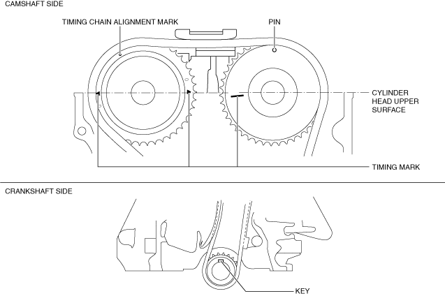
1. Verify that the timing marks and the key are aligned to the position shown in the figure.
ac5wzw00010919
|
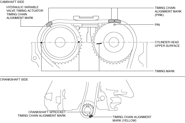
2. Install the timing chain while aligning the marks on each sprocket and the timing chain as shown in the figure.
ac5wzw00010920
|
3. Install the chain guide (No.1).
4. Install the tensioner arm.
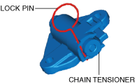
5. Install the chain tensioner.
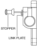
6. After installing the chain tensioner, remove the installed wire or paper clip, and then apply tension to the timing chain. (Chain tensioner (type A))
am3uuw00008861
|
7. After installing the timing chain tensioner, remove the installed rod, and then apply tension to the timing chain. (Chain tensioner (type B))
ac5uuw00006989
|
8. Verify that there is no looseness in the timing chain, and re-verify that each sprocket is in the specified location.
9. Rotate the crankshaft clockwise two turns and inspect the valve timing.
ac5wzw00010907
|
Engine Front Cover Assembly Note
bpe8ze00000007
|
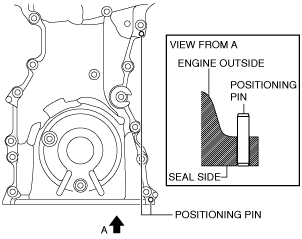
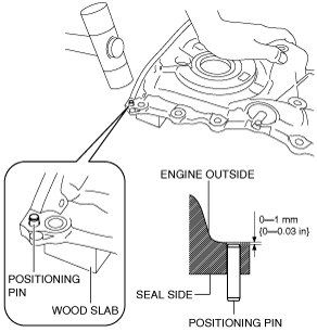
1. If the engine front cover is newly replaced, tap the positioning pins in the two locations to the seal surface side.
bpe1ze00000007
|
bpe7ze00000033
|
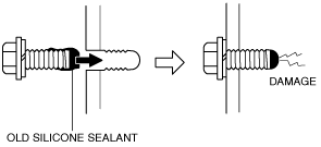
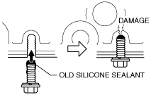
2. When reusing the engine front cover installation bolts, clean any old sealant from the bolts.
3. Completely clean and remove any oil, dirt, silicone sealant or other foreign matter that may be adhering to the engine front cover, cylinder head, and cylinder block.
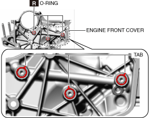
4. Install new O-rings to the engine front cover.
ac5wzw00010922
|
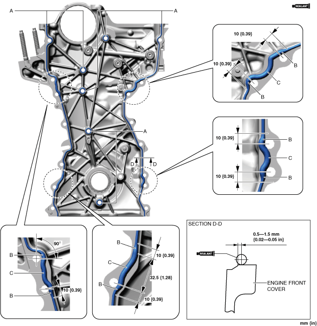
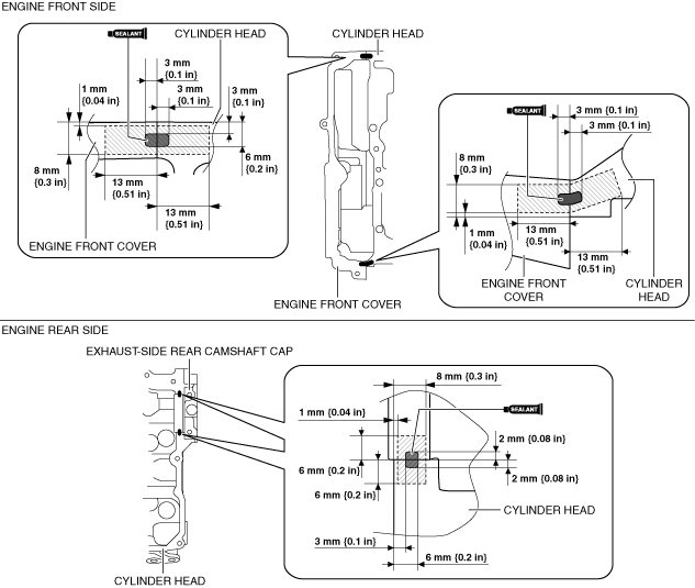
5. Apply silicone sealant (TB1217D or equivalent) to the engine front cover as shown in the figure.
btstze00000032
|
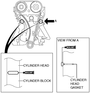
6. Apply silicone sealant (TB1217D or equivalent) to the areas shown in the figure.
am3uuw00008866
|
7. Install the engine front cover to the engine.
bpe8ze00000008
|
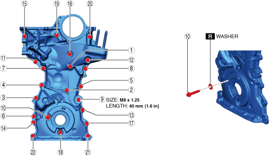
8. Prepare an appropriate M8 x 1.25 bolt (length 40 mm {1.6 in}).
9. Tighten the engine front cover installation bolts in the order shown in the figure.
ac5wzw00010925
|
10. Tighten the engine front cover stud bolts.
ac5wzw00010926
|
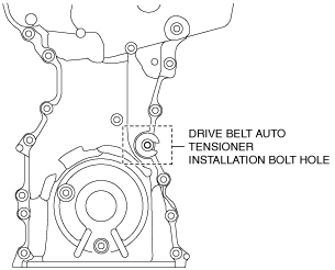
11. Remove the bolt installed to the drive belt auto tensioner installation bolt hole when installing the drive belt auto tensioner.
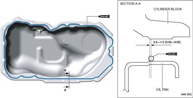
Oil Pan Assembly Note
1. Completely clean and remove any oil, dirt, sealant or other foreign matter that may be adhering to the cylinder block and oil pan.
2. When reusing the oil pan installation bolts, clean any old sealant from the bolts.
bpe8ze00000034
|
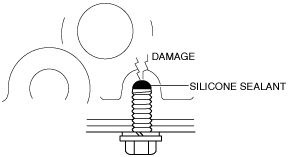
3. Apply silicone sealant (TB1217D or equivalent) to the oil pan along the inside of the bolt holes as shown in the figure.
btstze00000033
|
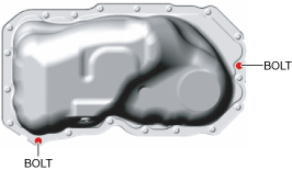
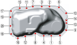
4. Install the oil pan using the following procedure:
ac5wzw00007107
|
btstze00000034
|
btstze00000035
|
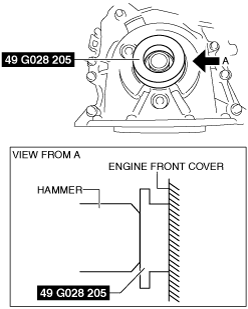
Front Oil Seal Assembly Note
1. Apply clean engine oil to the inner surface of a new front oil seal.
2. Insert the front oil seal into the engine front cover by hand.
3. Tap the front oil seal in evenly using the SST and a hammer.
am3uuw00008830
|
bpe1ze00000110
|
Crankshaft Pulley Lock Bolt Assembly Note
1. Hold the crankshaft using the SST.
bpe1ze00000069
|
2. Tighten the crankshaft pulley lock bolt in the order shown in the following two steps.
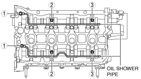
Oil Shower Pipe Assembly Note
1. Install the oil shower pipe in the order shown in the figure.
am3zzw00012759
|
Tightening torque
|
Installation position |
Tightening torque |
|---|---|
|
1
|
9—12 N·m {92—122 kgf·cm, 80—106 in·lbf}
|
|
2, 3
|
8.0—9.0 N·m {82—91 kgf·cm, 71—79 in·lbf}
|
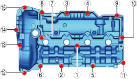
Cylinder Head Cover Assembly Note
1. Insert a new cylinder head cover gasket into the cylinder head cover groove.
2. Apply silicone sealant (TB1217D or equivalent) to the areas shown in the figure.
btstze00000036
|
3. Install the cylinder head cover.
4. Temporarily tighten the cylinder head cover bolts.
5. Tighten the cylinder head cover bolts in the order shown in the following 3 steps.
ac5wzw00010928
|
6. Measure the tightening torque again and verify that it is 5.0 N·m {51 kgf·cm, 44 in·lbf} or more.