 |
am3zzw00035599
HYDRAULIC LASH ADJUSTER (HLA) REMOVAL/INSTALLATION [SKYACTIV-X 2.0]
id0110hf804100
1. Perform the [Fuel Line Safety Procedure] referring to [BEFORE SERVICE PRECAUTION]. (See BEFORE SERVICE PRECAUTION [SKYACTIV-X 2.0].)
2. Disconnect the negative battery terminal. (See NEGATIVE BATTERY TERMINAL DISCONNECTION/CONNECTION [(E)].)
3. Remove the engine cover. (See ENGINE COVER REMOVAL/INSTALLATION [SKYACTIV-X 2.0].)
4. Remove the cylinder head cover. (See CYLINDER HEAD COVER REMOVAL/INSTALLATION [SKYACTIV-X 2.0].)
5. Remove front under cover No.2. (See FRONT UNDER COVER No.2 REMOVAL/INSTALLATION.)
6. Remove the front splash shield. (See SPLASH SHIELD REMOVAL/INSTALLATION.)
7. Remove the electric variable valve timing motor/driver. (See ELECTRIC VARIABLE VALVE TIMING MOTOR/DRIVER REMOVAL/INSTALLATION [SKYACTIV-X 2.0].)
8. Remove the engine rear cover (upper). (See ENGINE REAR COVER REMOVAL/INSTALLATION [SKYACTIV-X 2.0].)
9. Remove the rear housing. (See ENGINE REAR COVER REMOVAL/INSTALLATION [SKYACTIV-X 2.0].)
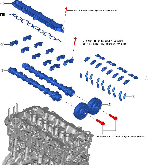
10. Remove using the procedure shown in the figure.
11. Install in the reverse order of removal.
12. Start the engine and inspect the following items.
am3zzw00035599
|
|
1
|
Injector holder
|
|
2
|
Electric variable valve timing actuator
|
|
3
|
Camshaft cap
|
|
4
|
Camshaft
|
|
5
|
Rocker arm
(See Rocker Arm Removal Note)
|
|
6
|
HLA
(See HLA Removal Note)
(See HLA Installation Note)
|
Electric Variable Valve Timing Actuator Removal Note
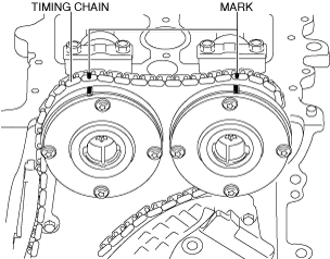
1. Mark the timing chain and each actuator with paint so that they can be reassembled in the same condition as before removal.
am3zzw00038134
|
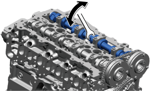
2. While moving the exhaust camshaft back and forth in the direction of the arrows using a wrench on the cast hexagon part, press down on the link plate of the timing chain tensioner with a thin flathead screwdriver (precision screwdriver) to unlock the plunger.
a59cjw00001954
|
am3zzw00038135
|
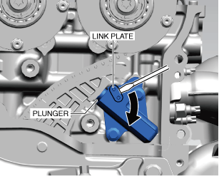
3. While holding down the link plate, slowly push the plunger back in the direction shown in the figure.
a59cjw00001968
|
4. Remove the screwdriver from the link plate with the plunger still pushed down.
5. Relieve some of the force from the plunger and move it back and forth 2—3 mm {0.08—0.11 in}.
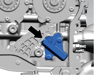
6. Insert a wire or paper clip with an approx. diameter of 1.5 mm {0.059 in} into the tensioner body at the point where the hole in the link plate overlaps the hole in the tensioner body to secure the link plate and lock the plunger.
am3zzw00038136
|
7. Remove chain guide No.1. (See TIMING CHAIN REMOVAL/INSTALLATION [SKYACTIV-X 2.0].)
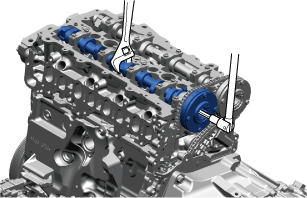
8. Secure the intake camshaft and the cast hexagon parts of the exhaust camshaft with a wrench and remove the electric variable valve timing actuator installation bolts.
a59cjw00001983
|
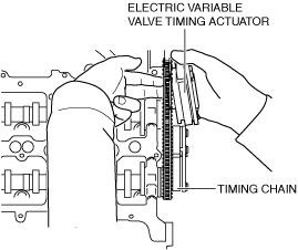
9. Using a screwdriver wrapped in a cloth, lightly press the electric variable valve timing actuator to the front and separate the intake camshaft and the exhaust camshaft from the actuator.
am3zzw00038137
|
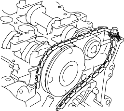
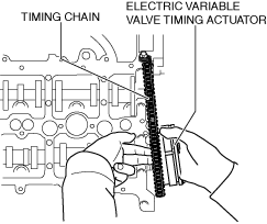
10. Remove the electric variable valve timing actuator by removing the timing chain from the exhaust and intake camshaft sprockets and set it aside to the rear side.
am3zzw00038138
|
11. Return the timing chain to the intake camshaft sprocket and pull up the timing chain using a rope as shown in the figure.
a59cjw00002289
|
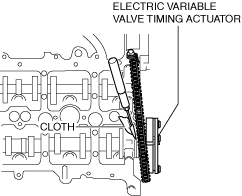
12. Using a screwdriver wrapped in a cloth, lightly push the electric variable valve timing actuator to the front and separate the intake camshaft and the actuator.
am3zzw00038139
|
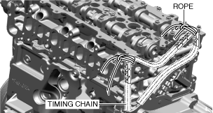
13. Remove the variable valve timing actuator by removing the timing chain from the intake and exhaust camshaft sprockets and set it aside to the front side.
am3zzw00038140
|
14. Pull up the timing chain and suspended it using a rope as shown in the figure.
am3zzw00038141
|
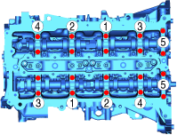
15. Loosen the camshaft cap bolts in a few passes in the order shown in the figure and remove the camshaft caps.
a59cjw00001987
|
Rocker Arm Removal Note
1. Arrange the rocker arms so that they can be reassembled to their original positions.
HLA Removal Note
1. Arrange the HLAs so that they can be reassembled to their original positions.
HLA Installation Note
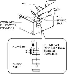
1. Bleed the air from the HLA using the following procedure.
am6xuw00007891
|
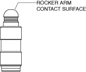
2. Visually inspect the HLA rocker arm contact surface for wear and damage.
am3uuw00008989
|
3. Assemble the HLAs to the same positions as before removal.
Rocker Arm Installation Note
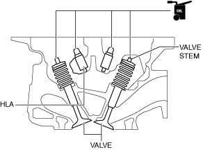
1. Apply engine oil to the ends of the HLAs and valve stems.
am3zzw00038142
|
Camshaft Installation Note
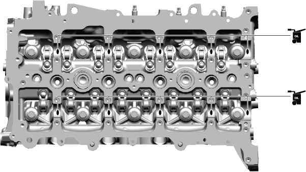
1. Apply SAE90 gear oil or equivalent, or engine oil to the positions shown in the figure.
a59cjw00002292
|
2. Apply SAE90 gear oil or equivalent, or engine oil to both thrust surfaces of each camshaft or both thrust surfaces of the camshaft caps.
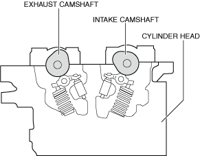
3. Align the cam position of cylinder No.1 around top dead center (TDC) and place the intake and exhaust camshafts on the cylinder head as shown in the figure.
am3zzw00038143
|
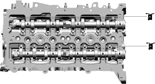
4. Apply SAE90 gear oil or equivalent, or engine oil to the central area of each journal on the camshaft.
a59cjw00002293
|
5. Tighten the camshaft cap installation bolts in 2 steps in the order shown in the figure.
a59cjw00001087
|
Electric Variable Valve Timing Actuator Installation Note
1. When replacing the electric variable valve timing actuator with a new one, mark the same positions with paint as those marked during removal.
2. Remove the rope suspending the timing chain from the intake side.
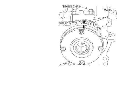
3. While aligning the paint mark on the timing chain marked during removal with the one on the electric variable valve timing actuator, engage the chain with the sprocket.
am3zzw00038144
|
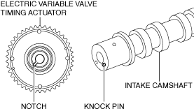
4. Align the knock pin on the end of the intake camshaft with the notch on the actuator side and assemble the actuator.
am3zzw00038145
|
5. Temporarily tighten the electric variable valve timing actuator installation bolt on the intake camshaft.
6. Remove the rope suspending the timing chain from the exhaust side.
7. While aligning the paint mark on the timing chain marked during removal with the one on the electric variable valve timing actuator, engage the chain with the sprocket.
am3zzw00038146
|
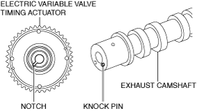
8. Align the knock pin on the end of the exhaust camshaft with the notch on the actuator side and assemble the actuator.
am3zzw00038147
|
9. Secure the cast hexagon parts of the intake and exhaust camshafts with a wrench and install the electric variable valve timing actuator installation bolts.
a59cjw00001983
|
10. Install the chain guide (No.1). (See TIMING CHAIN REMOVAL/INSTALLATION [SKYACTIV-X 2.0].)
11. Unlock the link plate on the tensioner body and apply tension to the timing chain.
12. Inspect the timing chain for looseness.
13. Verify that the paint marks on each sprocket and the timing chain are aligned.
am3zzw00038134
|
14. Rotate the crankshaft clockwise 2 times and verify that it rotates without any problems.