 |
am3zzw00030603
ENGINE MOUNT DISASSEMBLY/ASSEMBLY [SKYACTIV-D 1.8]
id0110t1806900
No.1 Engine Mount
1. Remove the front under cover No.2. (See FRONT UNDER COVER No.2 REMOVAL/INSTALLATION.)
2. Remove in the order indicated in the table.
3. Install in the reverse order of removal.
am3zzw00030603
|
|
1
|
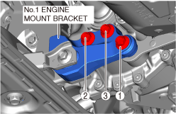
No.1 engine mount bracket
|
|
2
|
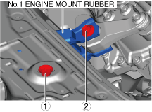
No.1 engine mount rubber
|
No.1 engine mount installation note
1. Tighten the No.1 engine mount bracket installation bolts in the order shown in the figure.
am3zzw00030604
|
2. Temporarily tighten the No.1 engine mount rubber installation bolts in the order shown in the figure.
am3zzw00030605
|
3. Tighten the No.1 engine mount rubber installation bolts in the order shown in the figure.
am3zzw00030605
|
No.3 Engine Mount
1. Disconnect the negative battery terminal. (See NEGATIVE BATTERY TERMINAL DISCONNECTION/CONNECTION [(E)].)
2. Remove the engine cover. (See ENGINE COVER REMOVAL/INSTALLATION [SKYACTIV-D 1.8].)
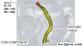
3. Disconnect the ground cable shown in the figure.
am3zzw00034400
|
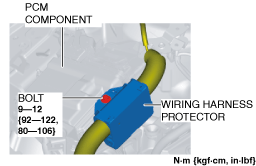
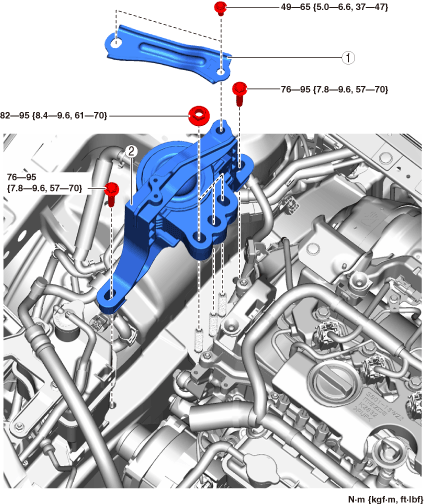
4. Remove the bolt shown in the figure and remove the wiring harness protector.
am3zzw00034401
|
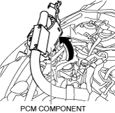
5. Set the PCM component aside with the PCM connector connected so that it does not interfere with the servicing. (See PCM REMOVAL/INSTALLATION [SKYACTIV-D 1.8].)
am2zzw00010275
|
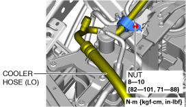
6. Remove the nut shown in the figure and set the cooler hose (LO) aside.
am3zzw00034402
|
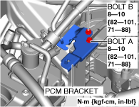
7. Remove the bolts shown in the figure and remove the PCM bracket.
am3zzw00034403
|
8. Remove the front under cover No.2. (See FRONT UNDER COVER No.2 REMOVAL/INSTALLATION.)
9. Remove in the order indicated in the table.
10. Install in the reverse order of removal.
am3zzw00024600
|
|
1
|
No.3 engine mount bracket
|
|
1
|
No.3 engine mount
|
No.3 engine mount removal note
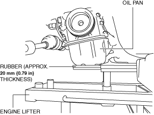
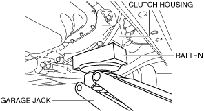
1. Remove the seal plate installed to the underside of the oil pan. (See OIL PAN REMOVAL/INSTALLATION [SKYACTIV-D 1.8].)
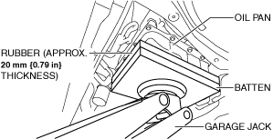
2. Before removing the No.3 engine mount, support the engine (oil pan) using a commercially available engine lifter or garage jack.
am3zzw00030608
|
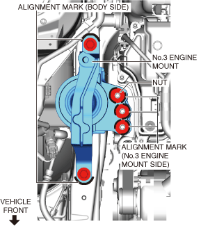
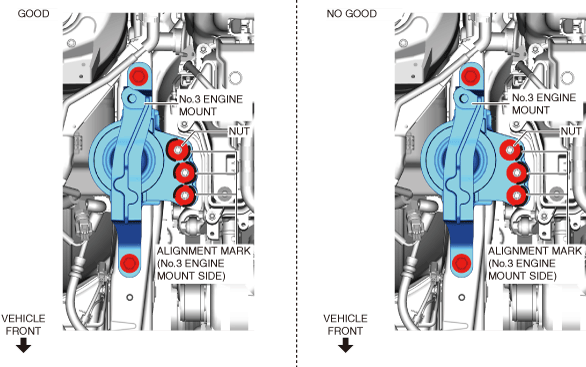
3. Place alignment marks on the locations shown in the figure so that they can be assembled to the same positions as before removal.
am3zzw00030609
|
4. Remove the No.3 engine mount.
No.3 engine mount installation note
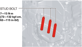
1. Tighten the engine front cover stud bolts.
am3zzw00034404
|
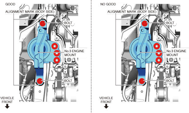
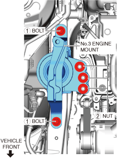
2. Temporarily tighten the No.3 engine mount installation bolts and nuts using the following procedure:
am3zzw00030610
|
am3zzw00030611
|
3. Tighten the No.3 engine mount installation bolts and nuts shown in the figure.
am3zzw00034646
|
4. Remove the engine lifter or garage jack.
5. Install the seal plate. (See OIL PAN REMOVAL/INSTALLATION [SKYACTIV-D 1.8].)
No.4 Engine Mount
1. Disconnect the negative battery terminal. (See NEGATIVE BATTERY TERMINAL DISCONNECTION/CONNECTION [(E)].)
2. Remove the following parts as a single unit: (See INTAKE-AIR SYSTEM REMOVAL/INSTALLATION [SKYACTIV-D 1.8].)
3. Remove the battery tray and PCM component. (See BATTERY REMOVAL/INSTALLATION [SKYACTIV-D 1.8].)
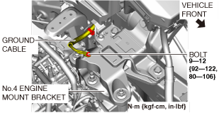
4. Remove the bolt shown in the figure and set the ground cable aside.
am3zzw00030613
|
5. Set the control cable aside. (MTX) (See CONTROL CABLE REMOVAL/INSTALLATION [C66M-R, C66MX-R].)
6. Remove the front under cover No.2. (See FRONT UNDER COVER No.2 REMOVAL/INSTALLATION.)
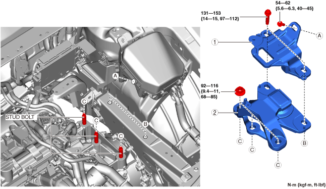
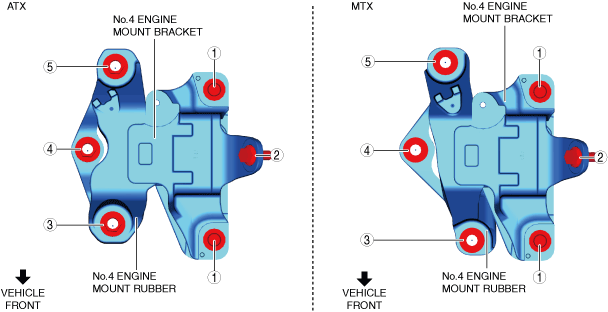
7. Remove in the order indicated in the table.
8. Install in the reverse order of removal.
am3zzw00034405
|
|
1
|
No.4 engine mount bracket
|
|
2
|
No.4 engine mount rubber
|
No.4 engine mount bracket removal note
am3zzw00030614
|
am3zzw00030615
|
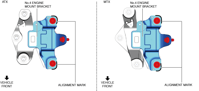
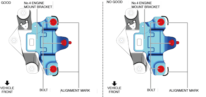
1. Place alignment marks on the locations shown in the figure so that they can be assembled to the same positions as before removal.
am3zzw00030616
|
2. Before removing the No.4 engine mount bracket, support the transaxle using a commercially available engine lifter or garage jack.
3. Remove the No.4 engine mount bracket.
No.4 engine mount rubber removal note
1. Before removing the No.4 engine mount rubber, support the transaxle using a commercially available engine lifter or garage jack.
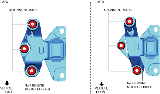
2. Place alignment marks on the locations shown in the figure so that they can be assembled to the same positions as before removal.
am3zzw00030617
|
3. Remove the No.4 engine mount rubber.
No.4 engine mount bracket and rubber installation note
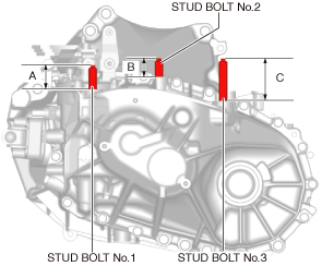
1. Measure the projection of the transaxle stud bolts. (MTX)
am3zzw00030618
|
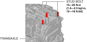
2. Tighten the transaxle stud bolts. (ATX)
am3zzw00034406
|
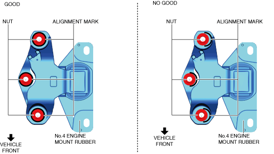
3. Align the alignment marks on the No.4 engine mount rubber and nuts, and temporarily tighten the nuts shown in the figure.
ATX
am3zzw00030620
|
MTX
am3zzw00030621
|
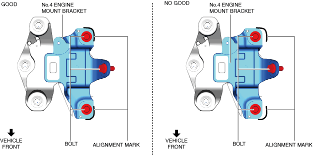
4. Align the alignment marks on the No.4 engine mount bracket and bolts, and temporarily tighten the bolts shown in the figure.
ATX
am3zzw00030622
|
MTX
am3zzw00030623
|
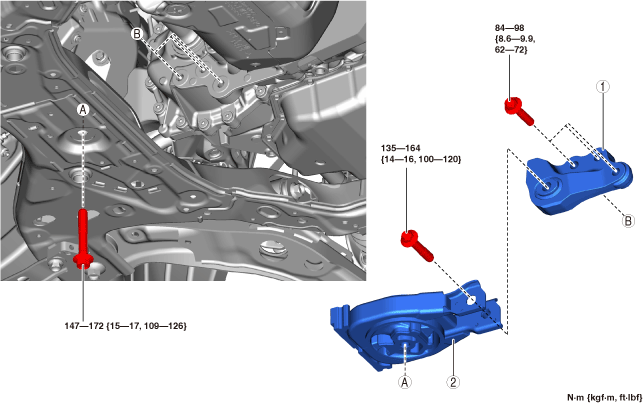
5. Install the No.4 engine mount bracket and rubber and temporarily tighten the nuts and bolts shown in the figure.
am3zzw00030624
|