 |
am3zzw00034382
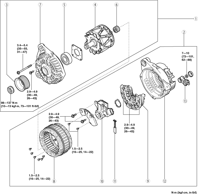
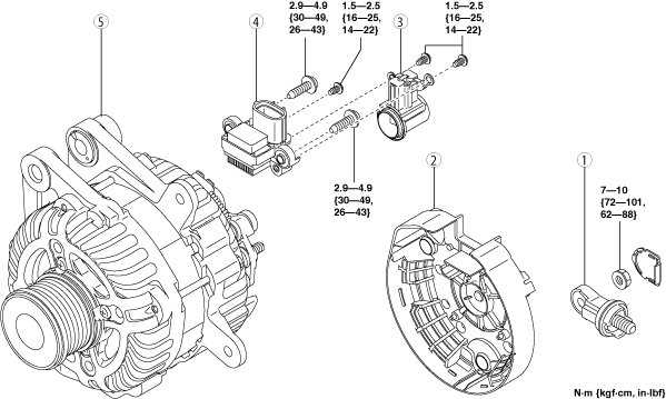
GENERATOR DISASSEMBLY/ASSEMBLY [SKYACTIV-G (WITH CYLINDER DEACTIVATION (E))]
id0117008004v3
1. Disassemble in the order indicated in the table.
2. Assemble in the reverse order of disassembly.
Applied VIN type A:
am3zzw00034382
|
|
1
|
Terminal B component
|
|
2
|
Rear cover
|
|
3
|
Brush holder
|
|
4
|
Regulator assy
|
|
5
|
Generator
|
Applied VIN type B:
MTX
am3zzw00038585
|
|
1
|
Rotor component
|
|
2
|
Stator coil component
|
|
3
|
Pulley
|
|
4
|
Rotor
|
|
5
|
Front bearing
|
|
6
|
Rear bearing
|
|
7
|
Front cover
|
|
8
|
Stator assy
|
|
9
|
Rectifier assy
|
|
10
|
Regulator assy
|
|
11
|
Brush set
(See Brush set Disassembly Note.)
(See Brush set Assembly Note.)
|
|
12
|
Cover.R
|
|
13
|
Terminal assy.B
|
ATX
am3zzw00038492
|
|
1
|
Rotor component
|
|
2
|
Stator coil component
|
|
3
|
Pulley
|
|
4
|
Rotor
|
|
5
|
Front bearing
|
|
6
|
Rear bearing
|
|
7
|
Front cover
|
|
8
|
Stator assy
|
|
9
|
Rectifier assy
|
|
10
|
Regulator assy
|
|
11
|
Brush set
(See Brush set Disassembly Note.)
(See Brush set Assembly Note.)
|
|
12
|
Cover.R
|
|
13
|
Terminal assy.B
|
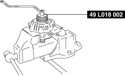
Pulley Disassembly/Assembly Note
1. Disassemble/assemble the pulley using the SST.
am3uuw00006095
|
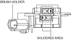
Brush set Disassembly Note
am2zzw00013282
|
1. Melt the solder and remove the brush from the brush holder.
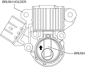
Brush set Assembly Note
am2zzw00013282
|
1. Press the brush into the brush holder with it facing in the direction shown in the figure.
am2zzw00013283
|
2. Solder the brush to the brush holder.