With Mazda M Hybrid
am3zzn00008684
|
Without Mazda M Hybrid
am3zzn00008685
|

am3zzn00008270
|

atsuzn00000587
|
CRUISE CONTROL SYSTEM [SKYACTIV-G (WITH CYLINDER DEACTIVATION (E))]
id0120u3903400
Cruise Control System
Outline
Function
|
Component parts |
Functions |
||
|---|---|---|---|
|
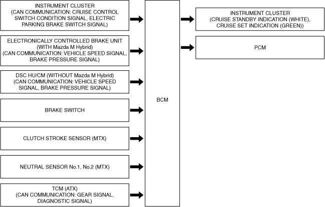
BCM
|
The BCM has the following functions.
• Recognizes the set vehicle speed set by the driver based on the cruise control switch operation signal sent from the instrument cluster.
• Sends the set vehicle speed and the system status display request signals to the instrument cluster based on the recognized set vehicle speed.
• Sends the target acceleration speed signal to the PCM based on the recognized set vehicle speed.
|
||
|
Instrument cluster
|
CAN communication: cruise control switch condition signal
|
Cruise switch
|
The cruise control system main switch.
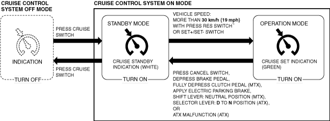
Cruise control system off
• By operating the switch, the cruise control system turns off.
Cruise control system standby
• By operating the switch, the cruise control system goes on standby.
|
|
CANCEL switch
|
The cruise control system cancel switch. While the cruise control system is operating, it goes on standby operating the switch.
|
||
|
RES switch
|
By operating the switch while the cruise control system is on standby and the vehicle is driven normally at more than 30 km/h {19 mph}, the PCM performs engine control so that the vehicle speed reaches the set vehicle speed stored in the BCM. (Operates when the BCM stores the previously set vehicle speed.)
|
||
|
SET+ switch
SET- switch
|
Cruise control system setting
• By operating the switch while the vehicle is driven normally at more than 30 km/h {19 mph}, the vehicle speed at the time the switch is pressed is stored in the BCM as the set vehicle speed, and the PCM performs engine control so that the vehicle speed reaches the set vehicle speed.
• Acceleration is controlled by pressing the SET+ switch or continuously pressing it.
• Deceleration is controlled by pressing the SET- switch or continuously pressing it.
|
||
|
Cruise standby indication (white)
|
|||
|
Cruise set indication (green)
|
|||
|
Electronically controlled brake unit
|
CAN communication: vehicle speed signal
|
The electronically controlled brake unit sends the vehicle speed signal to the BCM.
|
|
|
CAN communication: brake pressure signal
|
If the brake pressure exceeds 1.0 MPa {10 kgf/cm2, 145 psi}, the cruise control system goes on standby. (The pre-set vehicle speed is stored.)
|
||
|
CAN communication: electric parking brake switch signal
|
When the electric parking brake is applied, the cruise control system goes on standby. (The pre-set vehicle speed is stored.)
|
||
|
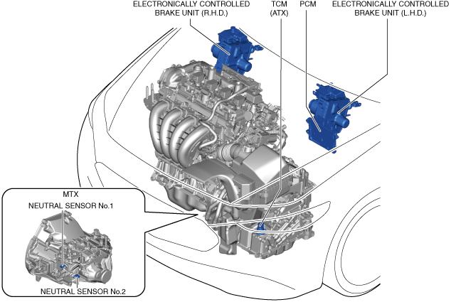
TCM (ATX)
|
CAN communication: gear signal
|
• When the selector lever is shifted from D to N position during cruise control, the cruise control system goes on standby. (The pre-set vehicle speed is stored.)
• The cruise control system does not operate when the selector lever is in the N, R or P position.
• The cruise control system does not go on standby during cruise control even if the selector lever is shifted from the D to M position.
|
|
|
PCM
|
The PCM performs engine control to maintain the set vehicle speed based on the target acceleration speed signal from the BCM.
|
||
|
Brake switch
|
When the brake pedal is pressed during cruise control, the cruise control system goes on standby. (The pre-set vehicle speed is stored.)
|
||
|
Clutch stroke sensor (MTX)
|
When the clutch pedal is pressed during cruise control, the cruise control system goes on standby. (The pre-set vehicle speed is stored.)
|
||
|
Neutral sensor No.1, No.2 (MTX)
|
When the shift lever is shifted to the neutral position during cruise control, the cruise control system goes on standby. (The pre-set vehicle speed is stored.)
|
||
Structure/construction
With Mazda M Hybrid
am3zzn00008684
|
Without Mazda M Hybrid
am3zzn00008685
|
am3zzn00008270
|
atsuzn00000587
|
am3zzn00010986
|
Operation
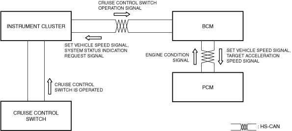
1. When the cruise control switch is operated, the BCM recognizes the set vehicle speed that was set by the driver based on the cruise control switch operation signal sent from the instrument cluster.
2. The BCM sends the set vehicle speed signal and a system status indication request signal to the instrument cluster based on the recognized set vehicle speed.
3. The BCM sends the target acceleration speed signal to the PCM based on the recognized set vehicle speed.
4. The PCM performs engine control to maintain the set vehicle speed based on the target acceleration speed signal from the BCM.
5. The instrument cluster displays the system operation screen based on the set vehicle speed signal and system status indication request signal from the BCM.
am3zzn00008683
|
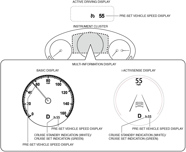
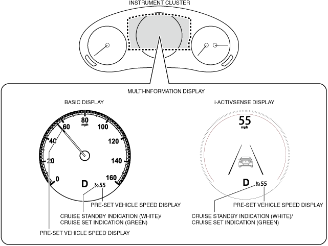
Cruise Standby Indication (White), Cruise Set Indication (Green)
Purpose
Function
am3zzn00009296
|
Construction
atsuzn00000591
|
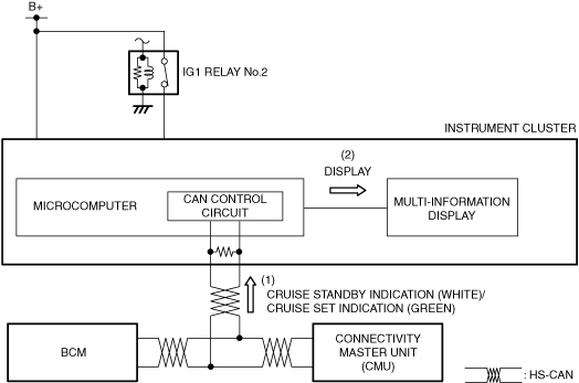
Operation
1. The instrument cluster receives (1) a cruise standby indication (white) illumination request signal or cruise control indication (green) illumination request signal from the BCM via CAN communication.
2. The instrument cluster displays (2) the cruise standby indication (white) or the cruise standby indication (green) on the multi-information display based on the cruise standby indication (white) illumination request signal or the cruise standby indication (green) illumination request signal.
atsuzn00000592
|