 |
am3zzn00007325
DRIVE SELECTION SYSTEM [SKYACTIV-G (WITHOUT CYLINDER DEACTIVATION (E))]
id0121u1000100
DRIVE SELECTION SYSTEM
Outline
Function
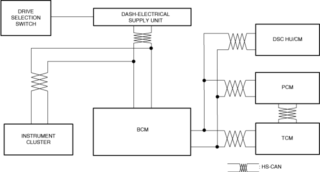
Block Diagram
am3zzn00007325
|
Operation
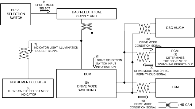
1. When sport mode is selected (1) using the drive selection switch, the Dash-Electrical Supply Unit sends a drive selection switch input information (2) to the BCM via CAN communication.
2. The PCM determines (3) the drive mode switching permit/hold based on each kind of information from the PCM, TCM, and the DSC, and sends the drive mode switching permit/hold signal (4) to the BCM via CAN communication.
3. When the BCM receives the select mode switch input information and the drive mode switching permit/hold signal, it determines the drive mode switching (5) based on it. At this time, the drive mode condition signal (6) sent to the PCM and TCM, and the indicator light illumination request signal (7) sent to the instrument cluster are sent via CAN communication.
4. After the PCM and TCM receive the drive mode condition signal, control change and shift point change are performed based on the accelerator opening angle.
5. When an indicator light illumination request signal is received, the instrument cluster turns on the select mode indicator (8).
am3zzn00006849
|
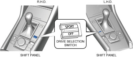
DRIVE SELECTION SWITCH
Purpose/Function
Construction
am3zzn00009598
|
Operation
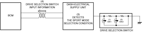
1. When the drive selection switch is pressed to the [SPORT] side (front side), contact point SW1 of the drive selection switch closes (1), and contact point SW2 closes (2) when the switch is pressed to the [OFF] side (rear side).
2. The Dash-Electrical Supply Unit detects (3) the sport mode selection condition based on the open/close of contact points SW1 and SW2 of the drive selection switch.
3. The Dash-Electrical Supply Unit sends (4) the drive selection switch input information to the BCM.
L.H.D.
am3zzn00010395
|
R.H.D.
am3zzn00010396
|
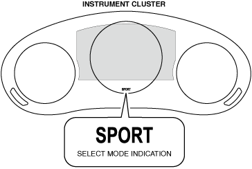
SELECT MODE INDICATION
Purpose
Function
Construction
am3zzn00006852
|
Operation
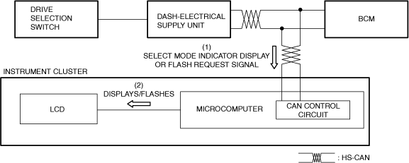
1. The instrument cluster receives (1) a select mode indicator display or flash request signal from the BCM via CAN communication.
2. The instrument cluster displays/flashes (2) the select mode indicator on the LCD based on the select mode indicator display request signal or the select mode indicator flash request signal.
am3zzn00006851
|