FUEL INJECTION AMOUNT CONTROL [SKYACTIV-D 1.8]
id0140s1987900
Outline
• The fuel injection amount is controlled by the opening of the nozzle in the fuel injector based on the signal from the PCM.
• The PCM learns and corrects the variation in the fuel injection amount of each cylinder.
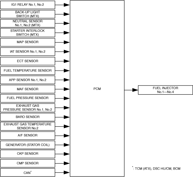
Block Diagram
Operation
• The PCM calculates the fuel injection amount according to engine operation conditions.
• The fuel injection amount is determined according to the engine conditions.
Normal operation:
-
• The value determined from the accelerator pedal opening angle and the engine speed is corrected and determined according to the vehicle conditions*1.
Engine protection/fail-safe:
-
• Any of the following operations is determined according to the engine conditions.
-
• Decrease correction to normal fuel injection amount (such as when engine coolant temperature is high)
• Fix fuel injection amount (small amount) possible for limp-home driving (such as when APP sensor is malfunctioning)
*1 :Each type of temperature/pressure, gear position, electric power generation condition, A/C condition, and other
Fuel cut
-
• If any of the following conditions are met, the PCM performs fuel-cut.
Fuel Cut Table
|
Control name
|
Control outline
|
|
Excessive engine speed fuel cut
|
Purpose
• Engine protection
Control conditions
• Engine speed is 5,600 rpm or more under load, 4,000 rpm or more under no load
|
|
Deceleration fuel cut
|
Purpose
• Improved fuel economy
Control conditions
• When engine conditions are as follows:
-
― Accelerator pedal is fully closed
― Engine speed is specified value or more
― Vehicle speed is specified value or more
|
|
Sensor malfunction fuel cut
|
Purpose
• To prevent engine damage from abnormal combustion caused by the inability to determine the piston position correctly due to an engine speed signal input error.
Control conditions
• Malfunction in the CKP sensor is detected
|
|
Theft prevention
|
Purpose
• To prevent theft
Control conditions
• Immobilizer system related information (engine start prohibited) received from BCM
|
|
Part protection (MTX)
|
Purpose
• Protection of dual-mass flywheel
Control conditions
• With the transaxle in gear, a condition continues for 2 s in which the vehicle engine speed is 500 rpm or less.
|
|
Fuel-cut at time of collision
|
Purpose
• For safety assurance
Control conditions
• Fuel cut request signal received from SAS control module
|
Fuel injection amount learning
-
• The correction amount is recorded in the PCM as a learned value, and remains recorded until it is updated.
Auto-learning
-
• Engine coolant temperature: 70—95 °C {158—203 °F}
• Not during engine stop by i-stop control
• DPF regeneration control not implemented
-
• If any of the implementation conditions is not met during the fuel injection amount learning, the fuel injection amount learning is canceled, but it will resume when the implementation conditions are met again.
Manual learning
-
― The fuel injection amount learning can be implemented using the Mazda Modular Diagnostic System (M-MDS) or a check connector.
Cruise control system
-
• The PCM controls the actual vehicle speed to reach the vehicle speed set by the BCM.
• The cruise control includes the cruise control operation condition and the cruise control stop condition.
-
Cruise control operation condition
-
• When all of the following conditions are met, execution of the cruise control system is enabled (cruise control standby status).
-
• Cruise switch: On
• Vehicle speed: Exceeds 30 km/h {19 mph}
-
Cruise control stop condition
-
• When any of the following conditions are met even while in cruise control, the PCM and BCM stops the cruise control and clears the set vehicle speed.
-
― Ignition: Off
― Press the cruise switch again
― Cruise control related DTCs detected
• When any of the following conditions are met even while in cruise control, the PCM stops the cruise control while storing the set vehicle speed.
-
― CANCEL switch: On
― Transaxle range sensor: P/N position (ATX)
― Clutch pedal depressed (MTX)
― Neutral position (MTX)
― Vehicle speed: Less than 20 km/h {12 mph}
― Brake switch: On (brake pedal depressed)
― Brake fluid pressure: 1.0 MPa {10 kgf/cm2, 145 psi} or more
― Electric parking brake switch : ON
-
Cruise control function
-
• The cruise control includes resume, tap-down, tap-up and downshift functions.
Function List
|
Function
|
Contents
|
|
Resume
|
• When the RESUME switch signal is input to the BCM during regular driving (cruise control is stopped) and the previously set vehicle speed is stored in the BCM, the PCM sets the set vehicle speed to the previously set vehicle speed and begins control.
|
|
Tap-up
|
• When all of the following conditions are met while driving the vehicle using cruise control, the PCM controls the actual vehicle speed to reach the vehicle speed set by the BCM.
SET+ switch is pressed:
-
― The set vehicle speed increases 1 km/h {0.6 mph}.
SET+ switch is pressed continuously:
-
― The set vehicle speed increases 10 km/h {6.2 mph}.
|
|
Tap down
|
• When all of the following conditions are met while driving the vehicle using cruise control, the PCM controls the actual vehicle speed to reach the vehicle speed set by the BCM.
SET- switch is pressed:
-
― The set vehicle speed decreases 1 km/h {0.6 mph}.
SET- switch is pressed continuously:
-
― The set vehicle speed decreases 10 km/h {6.2 mph}.
|
|
Downshift
|
• When the following conditions are met, a downshift signal is sent to the TCM via CAN.
-
― Target vehicle acceleration is not reached
• If the increase in vehicle speed on the down slope is high, the PCM sends a down shift signal to the TCM.
|
Brake override system
-
Brake override system operation conditions
-
• The brake override system prioritizes the brake operation if the accelerator pedal remains depressed and it cannot release due to a malfunction in the related accelerator pedal. In addition, if the accelerator pedal and brake pedal are depressed simultaneously, the brake override system reduces the fuel injection amount until the vehicle stops completely after decelerating the vehicle safely.
|
Operation start conditions
|
• When all of the following conditions are met with the accelerator pedal and brake pedal depressed, the PCM adjusts the fuel injection amount so that the engine speed is at 1,000 rpm.
While driving vehicle
-
― Accelerator pedal opening angle: 5% or more from fully closed
― Brake pedal: Depressed at specified depression or more
― Vehicle speed: 10 km/h {6.2 mph} or more
― Engine speed: 875 rpm or more
While vehicle is stopped
-
― Accelerator pedal opening angle: 5% or more from fully closed
― Brake pedal: Depressed at specified depression or more
― Shift lever position: neutral (MTX)
― Selector lever position: N position (ATX)
― Engine speed: 875 rpm or more
|
|
Operation complete conditions
|
• If the following conditions are met while the brake override system is operating, the PCM stops the operation of the brake override system and controls the fuel injection amount according to the accelerator pedal opening angle.
-
― Accelerator pedal not depressed
― Brake pedal not depressed
-
Note
-
• The brake override system operation stops by switching the ignition off.
|
-
Prevention of unnecessary brake override system operation
-
• If the servicing procedure requiring the brake pedal and the accelerator pedal to be depressed simultaneously is performed, unnecessary operation of the brake override system can be prevented, if necessary.
-
Note
-
• The operation of the emergency signal system (ESS) can be also canceled by performing the procedure for preventing unnecessary operation of the brake override system.
|
Cancel conditions
|
• If the releasing procedure is implemented with the following conditions met within 30 s after switching the ignition ON (KOEO), the brake override system does not operate until the recovery condition is met.
-
― Selector lever position: N position (ATX)
― Shift lever position: Neutral (MTX)
― Vehicle speed: 0 km/h {0 mph}
Releasing procedure
-
1. Depress the brake pedal for 10 s with the accelerator pedal released.
2. Repeatedly depress and release the accelerator pedal fully three times with the brake pedal depressed.
3. Release the brake pedal
|
|
Recovery condition
|
• The cancel conditions are reset when the ignition is switched off while the brake override system is canceled. As a result, the brake override system can operate.
|
-
Master warning light illumination request
-
• If any one of the following conditions is met, the PCM sends the master warning light illumination request signal to the instrument cluster. The master warning light illuminates to alert the driver that there is a malfunction in the brake system.
-
― Brake switch (No.1 signal) has a malfunction
― Brake switch (No.2 signal) has a malfunction
-
Master warning light flash request
-
• If the cancel condition for preventing unnecessary operation of the brake override system is implemented, the PCM sends a master warning light flash request signal to the instrument cluster. The driver is notified that the brake override system has been cancelled by the flashing of the master warning light.
Fail-safe
-
• To prevent engine damage, the engine speed is restricted to 3,600 rpm or less when the engine coolant temperature is −10°C {14 °F} while the ignition is switched ON (KOER). (Maximum 190 s period)