49 G027 006
Installer

49 H027 002
Bearing remover

REAR SHOCK ABSORBER DISASSEMBLY/ASSEMBLY [(E)]
id0214009000x2
Special service tool (SST)
|
49 G027 006
Installer
|
|
49 H027 002
Bearing remover
|
|
Replacement part
|
Piston rod nut
Quantity: 1
Location of use: Rear shock absorber
|
Oil and Chemical Type
|
Rubber grease
Type: NIPPON GREASE RUBBER GREASE
|
1. Remove the rear shock absorber. (See REAR SHOCK ABSORBER REMOVAL/INSTALLATION [(E)].)
2. Remove in the order indicated in the table.
3. Install in the reverse order of removal.
am3zzw00024755
|
|
1
|
Cap
|
|
2
|
Piston rod nut
(See Piston Rod Nut Removal Note.)
|
|
3
|
Rear shock absorber
|
|
4
|
Dust boot, bump stopper, mounting rubber component
|
|
5
|
Dust boot
|
|
6
|
Bump stopper
|
|
7
|
Mounting rubber
|
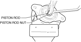
Piston Rod Nut Removal Note
1. Remove the piston rod nut using an offset box-end wrench and pliers.
am3zzw00036998
|
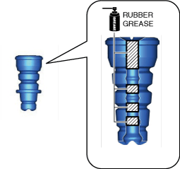
Dust Boot, Bump Stopper, Mounting Rubber Assembly Note
1. Wipe off grease on the bump stopper using a cloth.
2. Apply rubber grease to the inside of the bump stopper.
am3zzw00024756
|
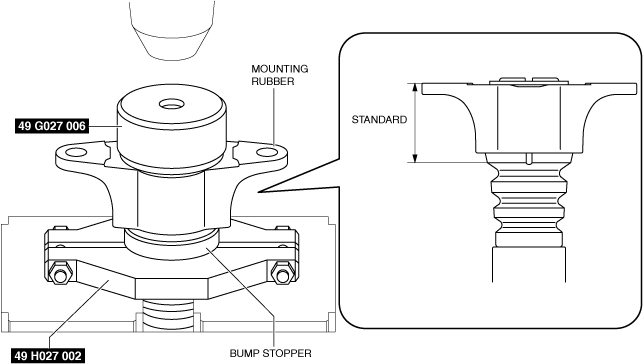
3. Assemble the bump stopper and the mounting rubber using the SSTs and a press.
am3zzw00027647
|
4. Verify that the assembly position of the bump stopper and the mounting rubber is within the standard.
5. Install the dust boot.
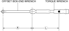
Piston Rod Nut Installation Note
1. Install the offset box-end wrench to the torque wrench as shown in the figure, set it on the piston rod nut, and measure dimensions A and L shown in the figure.
am3zzw00037046
|
2. Tighten the piston rod nut after calculating the tightening torque using the following formula.
am3zzw00037047
|