49 H027 002
Bearing remover

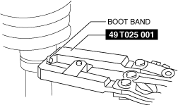
49 T025 001
Boot clamp crimpers
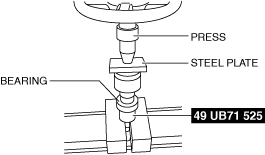
49 UB71 525
Bearing installer

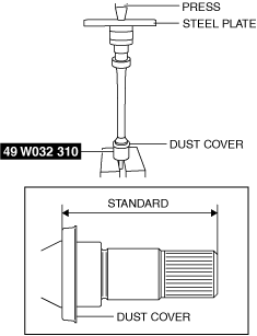
49 W032 310
Support block

49 0710 520
Universal bearing puller

—
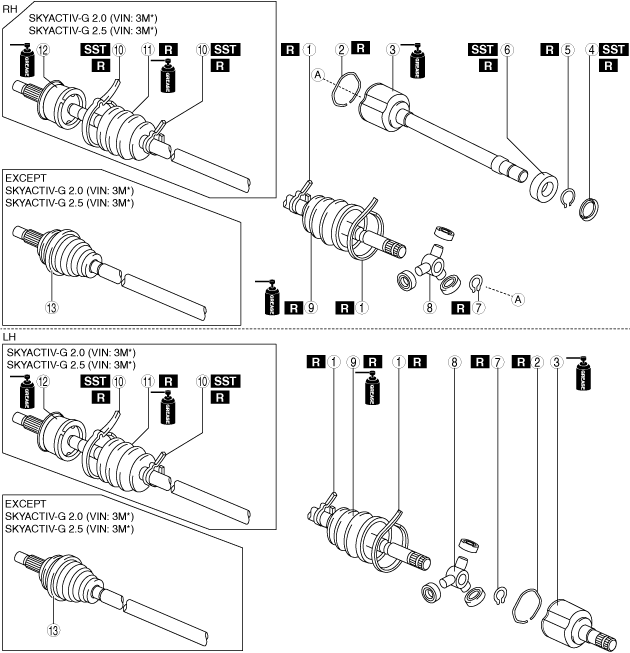
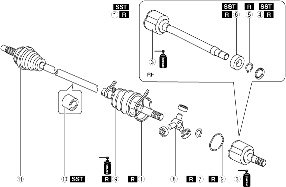
FRONT DRIVE SHAFT (TRIPOD JOINT) DISASSEMBLY/ASSEMBLY [(E)]
id0313008026y2
Special service tool (SST)
|
49 H027 002
Bearing remover
|
|
49 T025 001
Boot clamp crimpers
|
|
49 UB71 525
Bearing installer
|
|
|
49 W032 310
Support block
|
|
49 0710 520
Universal bearing puller
|
|
—
|
|
Replacement part
|
Boot band (transaxle side)
Quantity: 2
Location of use: Boot (transaxle side)
|
Dust cover
Quantity: 1
Location of use: Outer ring
|
Snap ring
Quantity: 1
Location of use: Outer ring
|
|
Clip
Quantity: 1
Location of use: Outer ring
|
Bearing
Quantity: 1
Location of use: Outer ring
|
Snap ring
Quantity: 1
Location of use: Tripod joint
|
|
Boot (transaxle side)
Quantity: 1
Location of use: Front drive shaft (transaxle side)
|
Boot band (wheel side)
Quantity: 2
Location of use: Boot (wheel side)
|
Boot (wheel side)
Quantity: 1
Location of use: Front drive shaft (wheel side)
|
Oil and chemical type
|
Grease
Type: Maintenance parts
|
1. Disassemble in the order shown in the figure.
2. Assemble in the reverse order of disassembly.
ATX
am3zzw00034695
|
|
1
|
Boot band (transaxle side)
|
|
2
|
Clip (VIN: Except 3M*)
|
|
3
|
Outer ring
|
|
4
|
Dust cover (With dust cover)
(See Dust Cover Disassembly Note.)
(See Dust Cover Assembly Note.)
|
|
5
|
Snap ring
|
|
6
|
Bearing
(See Bearing Disassembly Note.)
(See Bearing Assembly Note.)
|
|
7
|
Snap ring
|
|
8
|
Tripod joint
|
|
9
|
Boot (transaxle side)
|
|
10
|
Boot band (wheel side)
|
|
11
|
Boot (wheel side)
|
|
12
|
Shaft and ball joint component
|
|
13
|
Outer joint component
|
MTX
am3zzw00023110
|
|
1
|
Boot band (transaxle side)
|
|
2
|
Clip (VIN: Except 3M*)
|
|
3
|
Outer ring
|
|
4
|
Dust cover (With dust cover)
(See Dust Cover Disassembly Note.)
(See Dust Cover Assembly Note.)
|
|
5
|
Snap ring
|
|
6
|
Bearing
(See Bearing Disassembly Note.)
(See Bearing Assembly Note.)
|
|
7
|
Snap ring
|
|
8
|
Tripod joint
|
|
9
|
Boot (transaxle side)
|
|
10
|
Dynamic damper (With dynamic damper)
|
|
11
|
Outer joint component
|
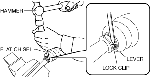
Boot Band (Transaxle Side) Disassembly Note (VIN: Except 3M*)
Type A
1. Using a flat chisel and hammer, lightly tap the lever of the boot band to disconnect the lock clip.
ac8wzw00002085
|
2. Remove the boot band using pliers.
ac8wzw00002086
|
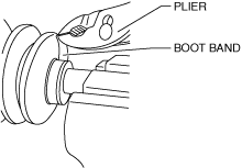
Type B
1. Grasp the boot band at the point shown in the figure using pliers, and remove the band.
ac5jjw00003246
|
Boot Band (Transaxle Side) Disassembly Note (VIN: 3M*)
Large diameter side
1. Grasp the boot band at the point shown in the figure using pliers, and remove the band.
ac5jjw00003246
|
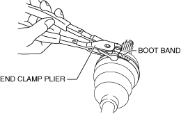
Small diameter side
1. Remove the boot band using end clamp pliers.
aatjjw00009759
|
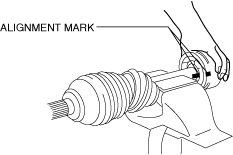
Clip, Outer Ring Disassembly Note (VIN: Except 3M*)
1. Place alignment marks on the shaft and outer ring.
am3zzw00036420
|
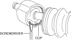
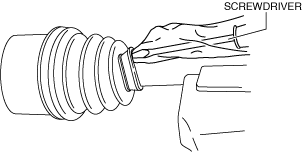
2. Remove the clip using a screwdriver.
am3zzw00023111
|
3. Remove the outer ring from the shaft.
4. Wipe off grease on the outer ring using a clean cloth.
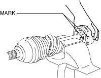
Outer Ring Disassembly Note (VIN: 3M*)
1. Place alignment marks on the shaft and outer ring.
am3zzw00036437
|
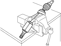
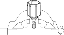
2. Secure the shaft in a vise.
am3zzw00036421
|
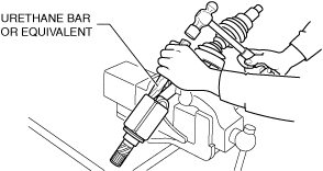
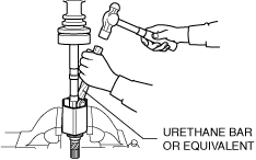
3. Lightly tap the outer ring evenly using a hammer and urethane bar or equivalent, and remove the outer ring from the shaft.
am3uuw00011974
|
4. Wipe off grease on the outer ring using a clean cloth.
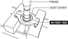
Dust Cover Disassembly Note
1. Remove the dust cover using a press and the SST.
ac8wzw00002089
|
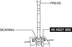
Bearing Disassembly Note
1. Remove the bearing using a press and the SST.
ac8wzw00002090
|
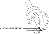
Snap Ring, Tripod Joint Disassembly Note
1. Place alignment marks on the shaft and tripod joint.
ac8wzw00002091
|
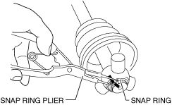
2. Remove the snap ring using snap ring pliers.
ac8wzw00002092
|
3. Remove the tripod joint from the shaft.
4. Wipe off grease on the shaft and tripod joint using a clean cloth.
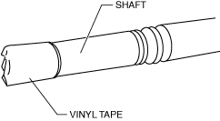
Boot (Transaxle Side) Disassembly Note
1. Wrap vinyl tape around the spline area of the shaft to prevent damage to the boot.
ac8wzw00002093
|
2. Remove the boot (transaxle side).
3. Wipe off grease on the boot (transaxle side) using a clean cloth.
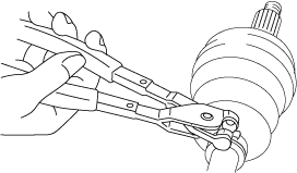
Boot Band (Wheel Side) Disassembly Note
1. Remove the boot band using end clamp pliers.
ac8wzw00002094
|
Boot (Wheel Side) Disassembly Note
1. Wrap vinyl tape around the spline area of the shaft to prevent damage to the boot.
ac8wzw00002093
|
2. Remove the boot (wheel side).
3. Wipe off grease on the boot (wheel side) and ball joint using a clean cloth.
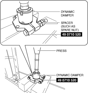
Dynamic Damper Disassembly Note [MTX]
1. Remove the dynamic damper using the SST, spacers (such as spare nuts), and a press.
am2zzw00007267
|
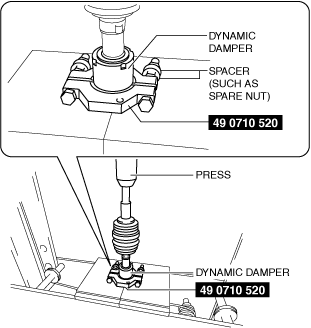
Dynamic Damper Assembly Note [MTX]
1. Apply soapy water to the inside of the dynamic damper.
2. Assemble the dynamic damper using the SST, spacers (such as spare nuts), and a press.
am6xuw00011607
|
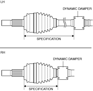
3. Verify that the installation position of the dynamic damper is within the specification.
am2zzw00007269
|
Specification
|
Engine type |
Installation position |
|
|---|---|---|
|
SKYACTIV-G 2.0 (VIN: JM*)
|
LH
|
281.6—286.6 mm {11.09—11.28 in}
|
|
SKYACTIV-G 2.0 (VIN: 3M*)
|
LH
|
275.5—281.5 mm {10.85—11.08 in}
|
|
RH
|
142.0—148.0 mm {5.591—5.826 in}
|
|
|
SKYACTIV-G 2.5
|
LH
|
280.9—286.9 mm {11.06—11.29 in}
|
|
SKYACTIV-X 2.0
|
LH
|
277.0—282.0 mm {10.91—11.10 in}
|
|
SKYACTIV-D 1.8
|
LH
|
287.9—292.9 mm {11.34—11.53 in}
|
Boot (Wheel Side) Assembly Note
1. Install the boot with the vinyl tape left wrapped around the spline area of the shaft.
2. Apply the specified grease to the ball joint and boot (wheel side).
Boot (wheel side) grease amount (MTX)
|
Engine type |
Grease amount |
|
|---|---|---|
|
SKYACTIV-G 1.5
|
LH
|
90—110 g {3.2—3.8 oz}
|
|
SKYACTIV-G 2.0 (VIN: JM*)
|
LH
|
90—110 g {3.2—3.8 oz}
|
|
SKYACTIV-G 2.0 (VIN: 3M*)
|
LH
|
93—103 g {3.3—3.6 oz}
|
|
RH
|
93—103 g {3.3—3.6 oz}
|
|
|
SKYACTIV-G 2.5
|
LH
|
95—115 g {3.4—4.0 oz}
|
|
SKYACTIV-X 2.0
|
LH
|
95—115 g {3.4—4.0 oz}
|
|
SKYACTIV-D 1.8
|
LH
|
90—110 g {3.2—3.8 oz}
|
Boot (wheel side) grease amount (ATX)
|
Engine type |
Grease amount |
|
|---|---|---|
|
SKYACTIV-G 1.5
|
LH
|
70—90 g {2.5—3.1 oz}
|
|
RH
|
70—90 g {2.5—3.1 oz}
|
|
|
SKYACTIV-G 2.0 (European (L.H.D. U.K.) specs)
|
LH
|
90—110 g {3.2—3.8 oz}
|
|
RH
|
90—110 g {3.2—3.8 oz}
|
|
|
SKYACTIV-G 2.0 (VIN: Except 3M*, Except European (L.H.D. U.K.) specs)
|
LH
|
70—90 g {2.5—3.1 oz}
|
|
RH
|
70—90 g {2.5—3.1 oz}
|
|
|
SKYACTIV-G 2.0 (VIN: 3M*)]
|
LH
|
93—103 g {3.3—3.6 oz}
|
|
RH
|
93—103 g {3.3—3.6 oz}
|
|
|
SKYACTIV-G 2.5 [VIN: JM*]
|
LH
|
90—110 g {3.2—3.8 oz}
|
|
RH
|
90—110 g {3.2—3.8 oz}
|
|
|
SKYACTIV-G 2.5 [VIN: 3M*]
|
LH
|
93—103 g {3.3—3.6 oz}
|
|
RH
|
93—103 g {3.3—3.6 oz}
|
|
|
SKYACTIV-X 2.0
|
LH
|
90—110 g {3.2—3.8 oz}
|
|
RH
|
90—110 g {3.2—3.8 oz}
|
|
|
SKYACTIV-D 1.8
|
LH
|
90—110 g {3.2—3.8 oz}
|
|
RH
|
90—110 g {3.2—3.8 oz}
|
|
3. Remove the vinyl tape.
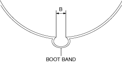
Boot Band (Wheel Side) Assembly Note
1. Adjust opening A of the SST to the standard by rotating the adjustment bolt.
ac8wzw00002095
|
2. Crimp the boot band using the SST.
ac8wzw00002096
|
3. Verify that crimp B of the boot band is within the standard.
ac8wzw00002097
|
4. Verify that the boot band does not protrude from the band assembly area.
Boot (Transaxle Side) Assembly Note
1. Insert the shaft through the boot (transaxle side) with the vinyl tape left wrapped around the spline area of the shaft.
2. Remove the vinyl tape wrapped around the spline of the shaft.
Tripod Joint, Snap Ring Assembly Note
1. Assemble the tripod joint with the shaft and tripod joint alignment marks aligned.
ac8wzw00002091
|
2. Assemble a new snap ring using snap ring pliers.
ac8wzw00002092
|
3. Verify that the snap ring is assembled correctly in the groove of the shaft.
Bearing Assembly Note
1. Install the new bearing using the SST and the press.
ac8wzw00002098
|
Dust Cover Assembly Note
1. Assemble a new dust cover using the SST and the press.
ac8wzw00002099
|
2. Verify that the installation position of the dust cover is within the standard.
Outer Ring, Clip Assembly Note (VIN: Except 3M*)
1. Apply the specified grease to the outer ring and boot (transaxle side).
Boot (transaxle side) grease amount (MTX)
|
Engine type |
Grease amount |
|
|---|---|---|
|
SKYACTIV-G 1.5
|
LH
|
135—155 g {4.77—5.46 oz}
|
|
SKYACTIV-G 2.0 (VIN: JM*)
|
LH
|
140—160 g {4.94—5.64 oz}
|
|
SKYACTIV-G 2.5
|
LH
|
165—185 g {5.83—6.52 oz}
|
|
SKYACTIV-X 2.0
|
LH
|
165—185 g {5.83—6.52 oz}
|
|
SKYACTIV-D 1.8
|
LH
|
140—160 g {4.94—5.64 oz}
|
Boot (transaxle side) grease amount (ATX)
|
Engine type |
Grease amount |
|
|---|---|---|
|
SKYACTIV-G 1.5
|
LH
|
130—150 g {4.59—5.29 oz}
|
|
RH
|
130—150 g {4.59—5.29 oz}
|
|
|
SKYACTIV-G 2.0 (European (L.H.D. U.K.) specs)
|
LH
|
135—155 g {4.77—5.46 oz}
|
|
RH
|
135—155 g {4.77—5.46 oz}
|
|
|
SKYACTIV-G 2.0 (VIN: Except 3M*, Except European (L.H.D. U.K.) specs)
|
LH
|
130—150 g {4.59—5.29 oz}
|
|
RH
|
130—150 g {4.59—5.29 oz}
|
|
|
SKYACTIV-G 2.5 [VIN: JM*]
|
LH
|
135—155 g {4.77—5.46 oz}
|
|
RH
|
135—155 g {4.77—5.46 oz}
|
|
|
SKYACTIV-X 2.0
|
LH
|
135—155 g {4.77—5.46 oz}
|
|
RH
|
135—155 g {4.77—5.46 oz}
|
|
|
SKYACTIV-D 1.8
|
LH
|
135—155 g {4.77—5.46 oz}
|
|
RH
|
135—155 g {4.77—5.46 oz}
|
|
2. Insert the outer ring to the shaft.
3. Assemble a new clip using a screwdriver.
am3zzw00023111
|
4. Assemble the boot (transaxle side) to the outer ring.
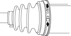
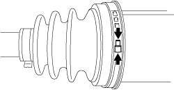
5. Set the drive shaft to the standard length.
Drive shaft (tripod joint) full length (MTX)
|
Engine type |
Full length (standard) |
|
|---|---|---|
|
SKYACTIV-G 1.5
|
LH
|
692.0—702.0 mm {27.25—27.63 in}
|
|
SKYACTIV-G 2.0 (VIN: JM*)
|
LH
|
663.3—673.3 mm {26.12—26.50 in}
|
|
SKYACTIV-G 2.5
|
LH
|
662.2—672.2 mm {26.08—26.46 in}
|
|
SKYACTIV-X 2.0 (2WD)
|
LH
|
658.5—668.5 mm {25.93—26.31 in}
|
|
SKYACTIV-X 2.0 (AWD)
|
LH
|
657.9—667.9 mm {25.91—26.29 in}
|
|
SKYACTIV-D 1.8
|
LH
|
670.6—680.6 mm {26.41—26.79 in}
|
Drive shaft (tripod joint) full length (ATX)
|
Engine type |
Full length (standard) |
|
|---|---|---|
|
SKYACTIV-G 1.5
|
LH
|
679.1—689.1 mm {26.74—27.12 in}
|
|
RH
|
1011.8—1021.8 mm {39.835—40.228 in}
|
|
|
SKYACTIV-G 2.0 (European (L.H.D. U.K.) specs)
|
LH
|
654.1—664.1 mm {25.76—26.14 in}
|
|
RH
|
1034.8—1044.8 mm {40.741—41.133 in}
|
|
|
SKYACTIV-G 2.0 (VIN: Except 3M*, Except European (L.H.D. U.K.) specs)
|
LH
|
653.7—663.7 mm {25.74—26.12 in}
|
|
RH
|
1034.7—1044.7 mm {40.737—41.129 in}
|
|
|
SKYACTIV-G 2.5 [VIN: JM*]
|
LH
|
654.1—664.1 mm {25.76—26.14 in}
|
|
RH
|
1035.1—1045.1 mm {40.752—41.145 in}
|
|
|
SKYACTIV-X 2.0
|
LH
|
649.1—659.1 mm {25.56—25.94 in}
|
|
RH
|
1030.4—1040.4 mm {40.567—40.960 in}
|
|
|
SKYACTIV-D 1.8
|
LH
|
670.7—680.7 mm {26.41—26.79 in}
|
|
RH
|
1017.1—1027.1 mm {40.044—40.437 in}
|
|
6. Release any trapped air from the boot by carefully lifting up the small end of the boot with a screwdriver wrapped in a clean cloth.
ac8wzw00002101
|
7. Verify that the drive shaft length is within the standard when the inside of the boot is at atmospheric pressure.
Outer Ring Assembly Note (VIN: 3M*)
1. Secure the outer ring in the vise.
ac5jjw00003262
|
2. Apply the specified grease to the outer ring and boot (transaxle side).
3. After aligning the shaft and outer ring alignment marks, lightly tap the tripod joint evenly using a hammer and urethane bar or equivalent, and insert the outer ring little by little while maintaining the shaft perpendicular.
am3uuw00012238
|
4. Assemble the boot (transaxle side) to the outer ring.
5. Set the drive shaft to the standard length.
Drive shaft (tripod joint) full length (standard)
|
Engine type |
Full length (standard) |
|
|---|---|---|
|
SKYACTIV-G 2.0 [MTX]
|
LH
|
658.3—668.3 mm {25.92—26.31 in}
|
|
RH
|
1021.0—1031.0 mm {40.197—40.590 in}
|
|
|
SKYACTIV-G 2.0 [ATX]
|
LH
|
645.3—655.3 mm {25.41—25.79 in}
|
|
RH
|
1030.5—1040.5 mm {40.571—40.964 in}
|
|
|
SKYACTIV-G 2.5 [ATX]
|
LH
|
645.3—655.3 mm {25.41—25.79 in}
|
|
RH
|
1027.0—1037.0 mm {40.434—40.826 in}
|
|
6. Release any trapped air from the boot by carefully lifting up the small end of the boot with a screwdriver wrapped in a clean cloth.
ac8wzw00002101
|
7. Verify that the drive shaft length is within the standard when the inside of the boot is at atmospheric pressure.
Boot Band (Transaxle Side) Assembly Note (VIN: Except 3M*)
Type A
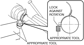
1. Apply rust prevention oil to the inside of the boot band.
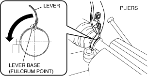
2. Lock the boot band against rotation using an appropriate tool as shown in the figure.
am3uuw00011981
|
3. Using a pair of pliers, grip the lever at the base (fulcrum point) and rotate it in the direction of the arrow.
am6xuw00011612
|
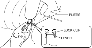
4. Hold the bent lever using a hand and secure it temporarily by pinching the lock clip using pliers.
ac8wzw00002102
|
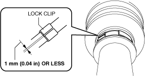
5. Lightly press the lock clip using a hammer so that the clearance of the lock clip is 1 mm {0.04 in} or less.
am3uuw00011984
|
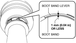
6. Verify that the clearance between the boot band and boot band lever is 1 mm {0.04 in} or less.
am3uuw00011985
|
7. After assembling the boot band, perform the following verification.
Type B
1. Grasp the boot band at the point shown in the figure using pliers and tighten the boot band.
am3zzw00013536
|
Boot Band (Transaxle Side) Assembly Note (VIN: 3M*)
Large diameter side
1. Grasp the boot band at the point shown in the figure using pliers and tighten the boot band.
am3zzw00013536
|
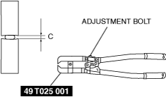
Small diameter side
1. Adjust opening C of the SST to the standard by rotating the adjustment bolt.
azzzcw00000102
|
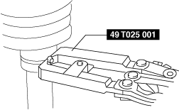
2. Crimp the boot band using the SST.
am3uuw00009858
|
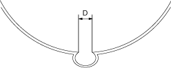
3. Verify that crimp D of the boot band is within the standard.
atstjw00000050
|
4. Verify that the boot band does not protrude from the band assembly area.