|
am3zzn00009133
ELECTRONICALLY CONTROLLED BRAKE UNIT
id042000002200
Electronically Controlled Brake Unit
Outline
HU part purpose, function
HU part construction
Main component parts and functions
|
Part name |
Function |
|---|---|
|
Master cylinder
|
• Converts the brake pedal depression amount by the driver to brake fluid pressure and sends it to the stroke simulator.
|
|
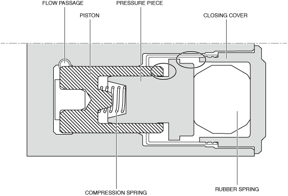
Stroke simulator
|
• Generates a brake pedal stroke and brake pedal depression response according to the brake pedal depression amount by the driver.
|
|
Linear actuator
|
• Generates the necessary brake fluid pressure according to the control signal from the CM part.
|
|
Pressure feed valve
|
• Sends the brake fluid pressure generated by the linear actuator to each caliper piston.
• If a malfunction occurs in the system, it blocks the hydraulic passage from the linear actuator to each caliper piston.
|
|
TMC cut valve
|
• During normal operation, it blocks the hydraulic passage from the master cylinder to each caliper piston.
• If a malfunction occurs in the system, the brake fluid pressure generated by the master cylinder is sent directly to each caliper piston.
|
|
Inlet solenoid valve
|
• Increases and maintains the brake fluid pressure by connecting/blocking the brake circuit according to the control signal from the CM part.
|
|
Outlet solenoid valve
|
• Decreases the brake fluid pressure by connecting/blocking the brake circuit according to the control signal from the CM part.
|
|
Simulator valve
|
• Sends the brake fluid pressure generated by the master cylinder to the stroke simulator.
• If a malfunction occurs in a system, it blocks the hydraulic passage from the master cylinder to the stroke simulator.
|
|
Diagnosis valve
|
―
|
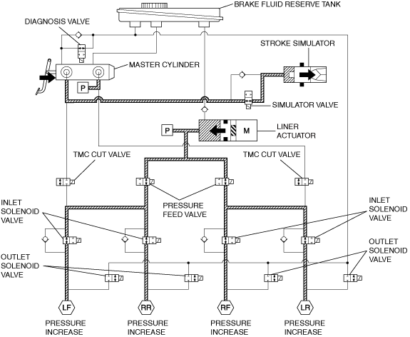
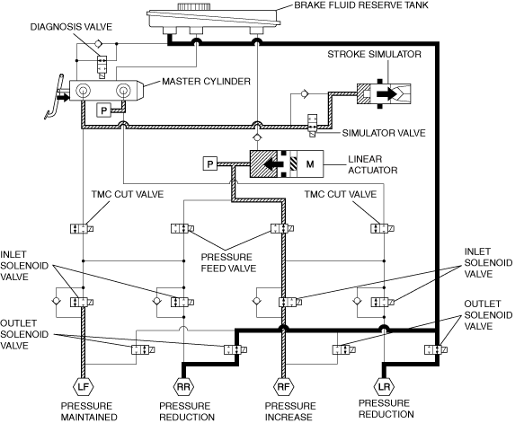
Hydraulic Circuit Diagram
am3zzn00009133
|
Master Cylinder
Purpose, function
am3zzn00009133
|
Construction
Operation
Stroke Simulator
Purpose, function
am3zzn00009133
|
Construction
am3zzn00009134
|
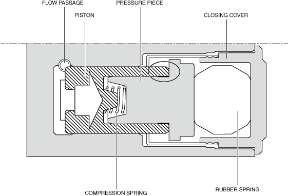
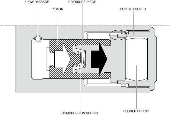
Operation
am3zzn00009135
|
am3zzn00009136
|
am3zzn00009137
|
Stroke Sensor
Purpose/function
Construction
Brake Fluid Pressure Sensor
Purpose/function
Construction
Linear Actuator
HU Part Operation
During normal braking
Solenoid valve operation table
|
Pressure feed valve |
TMC cut valve |
Inlet solenoid valve |
Outlet solenoid valve |
Simulator valve |
Linear actuator |
||||||||
|---|---|---|---|---|---|---|---|---|---|---|---|---|---|
|
LF―RR |
RF―LR |
LF―RR |
RF―LR |
LF |
RF |
LR |
RR |
LF |
RF |
LR |
RR |
||
|
ON (open)
|
ON (closed)
|
OFF (open)
|
OFF (closed)
|
ON (open)
|
Operation
|
||||||||
am3zzn00009138
|
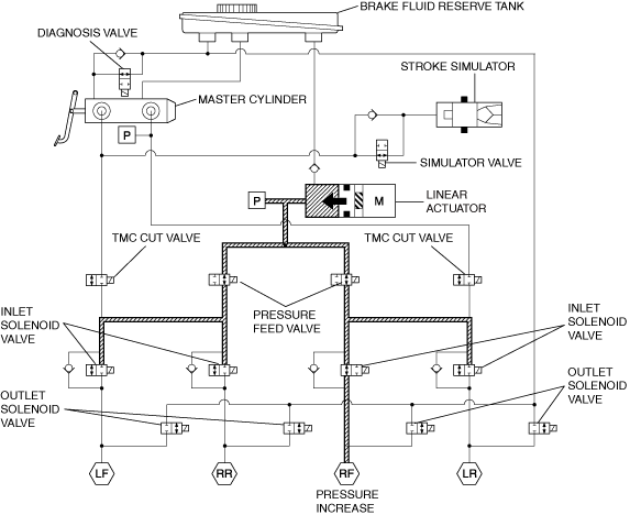
During ABS and EBD control
Solenoid valve operation table
|
Pressure feed valve |
TMC cut valve |
Inlet solenoid valve |
Outlet solenoid valve |
Simulator valve |
Linear actuator |
|||||||||
|---|---|---|---|---|---|---|---|---|---|---|---|---|---|---|
|
LF―RR |
RF―LR |
LF―RR |
RF―LR |
LF |
RF |
LR |
RR |
LF |
RF |
LR |
RR |
|||
|
Pressure increase mode
|
ON (open)
|
ON (closed)
|
OFF (open)
|
OFF (closed)
|
ON (open)
|
Operation
|
||||||||
|
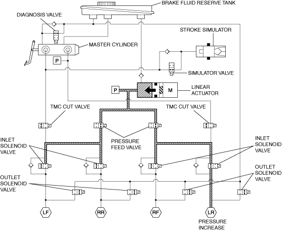
Hold mode
|
ON (open)
|
ON (closed)
|
ON (closed)
|
OFF (closed)
|
ON (open)
|
Operation
|
||||||||
|
Pressure decrease mode
|
ON (open)
|
ON (closed)
|
ON (closed)
|
ON (open)
|
ON (open)
|
Operation
|
||||||||
am3zzn00009139
|
During DSC control (oversteer tendency suppression) and during TCS control
Solenoid valve operation table
|
Pressure feed valve |
TMC cut valve |
Inlet solenoid valve |
Outlet solenoid valve |
Simulator valve |
Linear actuator |
|||||||||
|---|---|---|---|---|---|---|---|---|---|---|---|---|---|---|
|
LF―RR |
RF―LR |
LF―RR |
RF―LR |
LF |
RF |
LR |
RR |
LF |
RF |
LR |
RR |
|||
|
Pressure increase mode
|
ON (open)
|
ON (closed)
|
ON (closed)
|
OFF (open)
|
ON (closed)
|
OFF (closed)
|
ON (open)
|
Operation
|
||||||
|
Hold mode
|
ON (open)
|
ON (closed)
|
ON (closed)
|
OFF (closed)
|
ON (open)
|
OFF
|
||||||||
|
Pressure decrease mode
|
ON (open)
|
ON (closed)
|
ON (closed)
|
OFF (closed)
|
ON (open)
|
OFF (closed)
|
ON (open)
|
OFF
|
||||||
am3zzn00009140
|
During DSC control (understeer tendency suppression)
Solenoid valve operation table
|
Pressure feed valve |
TMC cut valve |
Inlet solenoid valve |
Outlet solenoid valve |
Simulator valve |
Linear actuator |
|||||||||
|---|---|---|---|---|---|---|---|---|---|---|---|---|---|---|
|
LF―RR |
RF―LR |
LF―RR |
RF―LR |
LF |
RF |
LR |
RR |
LF |
RF |
LR |
RR |
|||
|
Pressure increase mode
|
ON (open)
|
ON (closed)
|
ON (closed)
|
OFF (open)
|
ON (closed)
|
OFF (closed)
|
ON (open)
|
Operation
|
||||||
|
Hold mode
|
ON (open)
|
ON (closed)
|
ON (closed)
|
OFF (closed)
|
ON (open)
|
OFF
|
||||||||
|
Pressure decrease mode
|
ON (open)
|
ON (closed)
|
ON (closed)
|
OFF (closed)
|
ON (open)
|
OFF (closed)
|
ON (open)
|
OFF
|
||||||
am3zzn00009141
|
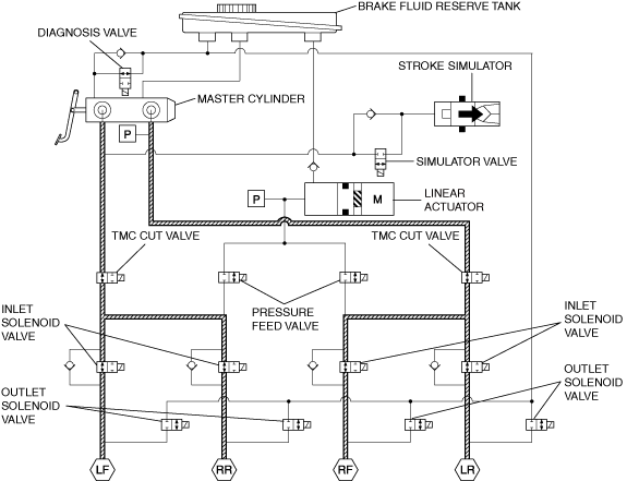
System malfunction
Solenoid valve operation table
|
Pressure feed valve |
TMC cut valve |
Inlet solenoid valve |
Outlet solenoid valve |
Simulator valve |
Linear actuator |
||||||||
|---|---|---|---|---|---|---|---|---|---|---|---|---|---|
|
LF―RR |
RF―LR |
LF―RR |
RF―LR |
LF |
RF |
LR |
RR |
LF |
RF |
LR |
RR |
||
|
OFF (closed)
|
OFF (open)
|
OFF (open)
|
OFF (closed)
|
OFF (closed)
|
OFF
|
||||||||
am3zzn00009142
|
CM Part Purpose, Function
Function Table
|
Function |
Content |
|---|---|
|
Regenerative brake coordinated control
|
• Controls the brake fluid pressure according to the difference between the deceleration speed by the ISG resistance (regenerative braking) and the deceleration speed requested by the driver.
|
|
Normal brake control
|
|
|
ABS control
|
• Maintains the directional stability during braking, assures steerability, and reduces the stopping distance by controlling the brake fluid pressure during braking.
|
|
EBD control
|
• Prevents the rear wheels from locking first during braking by constantly and optimally controlling the distribution of brake fluid pressure of the front and rear wheels according to the vehicle load, road conditions and the vehicle speed.
|
|
TCS control
|
• Improves acceleration from starts, acceleration performance, and safety by controlling the drive force so that the drive force is within the limits of the road surface friction according to the road and driving conditions.
|
|
DSC control
|
• Controls strong oversteer tendency and strong understeer tendency while turning by controlling the engine output and the brakes on each wheel to assure vehicle stability.
|
|
Electronic control brake assist function
|
• After determining emergency braking, hydraulic pressure higher than the normal brake hydraulic pressure is supplied to each wheel by controlling the brakes on each wheel.
• If a condition is detected in which emergency braking is anticipated by the change in speed of the accelerator pedal position, the gap between the brake pad and disc plate is reduced to enhance the response during braking.
|
|
AUTOHOLD
|
• Maintains the vehicle in a stopped condition using the brake fluid pressure hold function of the electronically controlled brake unit even if the brake pedal is released while the vehicle is stopped.
|
|
Vehicle roll prevention function
|
• Prevents the vehicle from moving during i-stop control (engine off) by drive torque transmission from engine revving when the foot is released from the brake pedal and the engine is restarted.
|
|
Hill Launch Assist (HLA) function
|
• When the vehicle is held at a stop by depressing the brake pedal on a slope with a grade of 6% (ATX vehicle), or 3% (MTX vehicle) or more, the brake fluid pressure is maintained to prevent the vehicle from rolling backwards even after the driver's foot is released from the brake pedal.
|
|
Secondary collision reduction system control function
|
• If the vehicle is hit by another vehicle and it is moved by the force of the collision, the brakes on the vehicle are automatically applied to mediate secondary collision damage, and the hazard lights are flashed at the same time to caution surrounding vehicles.
|
|
CAN communication function
|
• Information such as the wheel speed signal and DSC system warning control is output via CAN communication.
|
|
On-board diagnostic system
|
• A main component of the electronically controlled brake system includes the on-board diagnostic function. In case a malfunction occurs, warning lights or warning indicators turn on to alert the driver and, at the same time, a DTC is stored in the electronically controlled brake unit.
• As a result of the on-board diagnostics, if a malfunction is determined, it performs control to prevent loss of drive safety.
|
|
Automatic configuration function
|
• When the ignition is switched ON after the electronically controlled brake unit has been replaced, the electronically controlled brake unit reads data from the instrument cluster via CAN communication to perform automatic configuration.
|
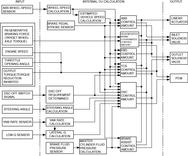
Block diagram
am3zzn00009143
|