|
1
|
RECORD VEHICLE STATUS WHEN DTC WAS DETECTED TO UTILIZE WITH REPEATABILITY VERIFICATION
• Record the freeze frame data/snapshot data.
-
Note
-
• Recording can be facilitated using the screen capture of the PC function.
|
—
|
Go to the next step.
|
|
2
|
VERIFY RELATED REPAIR INFORMATION OR SERVICE INFORMATION AVAILABILITY
• Verify related Service Bulletins, on-line repair information, or Service Information availability.
• Is any related Information available?
|
Yes
|
Perform repair or diagnosis according to the available information.
• If the vehicle is not repaired, go to the next step.
|
|
No
|
Go to the next step.
|
|
3
|
VERIFY PCM DTC
• Perform the PCM DTC inspection using the M-MDS.
• Are any DTCs present?
|
Yes
|
Go to the applicable DTC inspection.
|
|
No
|
Go to the next step.
|
|
4
|
INSPECT BATTERY CONNECTOR FOR MALFUNCTION
• Inspect the applicable connector and terminal.
• Are the connector and terminal normal?
|
Yes
|
Go to the next step.
|
|
No
|
Repair or replace the malfunctioning location and perform the repair completion verification.
|
|
5
|
INSPECT BATTERY FOR MALFUNCTION
• Inspect the applicable part.
• Is the part normal?
|
Yes
|
Go to the next step.
|
|
No
|
Repair or replace the malfunctioning location and perform the repair completion verification.
|
|
6
|
INSPECT GENERATOR (WITHOUT Mazda M Hybrid)/INTEGRATED STARTER GENERATOR (ISG) (WITH Mazda M Hybrid) FOR MALFUNCTION
• Inspect the applicable part.
• Is the part normal?
|
Yes
|
Go to the next step.
|
|
No
|
Repair or replace the malfunctioning location and perform the repair completion verification.
|
|
7
|
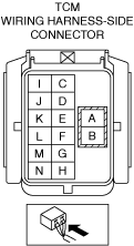
INSPECT TCM CONNECTOR AND TERMINALS
• Switch the ignition off.
• Disconnect the TCM connector.
• Visually inspect the TCM connector and terminals.
• Is there any malfunction?
|
Yes
|
Repair or replace the connector and/or terminals, then go to repair completion verification.
|
|
No
|
Go to the next step.
|
|
8
|
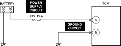
INSPECT TCM POWER SUPPLY CIRCUIT
• Always reconnect all disconnected connectors.
• Access the PID VPWR using the M-MDS.
• Is the PID value B+?
|
Yes
|
Go to the next step.
|
|
No
|
Inspect the F22 15 A fuse.
• If the fuse is blown:
-
― Refer to the wiring diagram and verify whether or not there is a common connector between F22 15 A fuse and TCM terminal A.
If there is a common connector:
-
• Determine the malfunctioning part by inspecting the common connector and the terminal for corrosion, damage, or pin disconnection, and the common wiring harness for a short to ground.
• Repair or replace the malfunctioning part.
If there is no common connector:
-
• Repair or replace the wiring harness which has a short to ground.
• Replace the fuse.
• If the fuse is deteriorated:
-
― Replace the malfunctioning fuse.
• If the fuse is normal:
-
― Refer to the wiring diagram and verify whether or not there is a common connector between battery positive terminal and TCM terminal A.
If there is a common connector:
-
• Determine the malfunctioning part by inspecting the common connector and the terminal for corrosion, damage, or pin disconnection, and the common wiring harness for an open circuit.
• Repair or replace the malfunctioning part.
If there is no common connector:
-
• Repair or replace the wiring harness which has an open circuit.
Go to the next step.
|
|
Repair completion verification
|
VERIFY DTC TROUBLESHOOTING COMPLETED
• Always reconnect all disconnected connectors.
• Clear the DTC using the M-MDS.
• Perform the following procedure to ensure that the DTC has been resolved:
-
1. Drive the vehicle for 5 s or more under the following condition:
-
• Selector lever position: D or R position
• Perform the DTC inspection using the M-MDS.
• Are any DTCs present?
|
Yes
|
Repair the malfunctioning location according to the applicable DTC troubleshooting.
|
|
No
|
DTC troubleshooting completed.
|