COUPLER COMPONENT REMOVAL/INSTALLATION [EV6A-EL]
id0517n2112400
-
Warning
-
• A hot transaxle and ATF can cause severe burns. Turn off the engine and wait until they are cool.
• Always wear protective eye wear when using the air compressor. If the air compressor is used, any particles of dirt or sludge could spatter and get into the eyes.
-
Caution
-
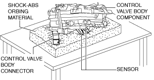
• Placing the control valve body connector side pointed downward could damage the control valve body connector part or sensor. If the servicing can only be performed by pointing the control valve body connector side downward, spread shock-absorbing material, which does not produce dust or foreign matter, and place the control valve body connector part and sensor on the table so that they do not directly contact the table.
1. Select the selector lever to P position.
2. Disconnect the negative battery terminal. (See NEGATIVE BATTERY TERMINAL DISCONNECTION/CONNECTION [(E)].)
3. Remove the front under cover No.1. (See FRONT UNDER COVER No.1 REMOVAL/INSTALLATION.)
4. Remove the front under cover No.2. (See FRONT UNDER COVER No.2 REMOVAL/INSTALLATION.)
5. Clean the transaxle exterior throughout with a steam cleaner or cleaning solvents.
6. Remove the following parts as a single unit. (See INTAKE-AIR SYSTEM REMOVAL/INSTALLATION [SKYACTIV-G (WITH CYLINDER DEACTIVATION (E))].)
-
• Air cleaner cover
• Air cleaner element
• Fresh-air duct
• Air cleaner case
• Air hose
• Resonance chamber
7. Drain the ATF. (See AUTOMATIC TRANSAXLE FLUID (ATF) REPLACEMENT [EV6A-EL].)
8. Remove the control valve body. (See CONTROL VALVE BODY REMOVAL/INSTALLATION [EV6A-EL].)
9. Remove the oil seal (control valve body). (See OIL SEAL (CONTROL VALVE BODY) REPLACEMENT [EV6A-EL].)
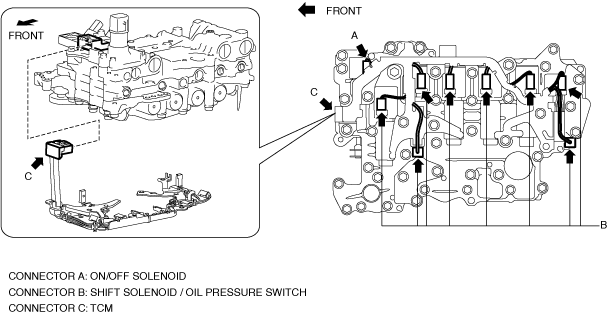
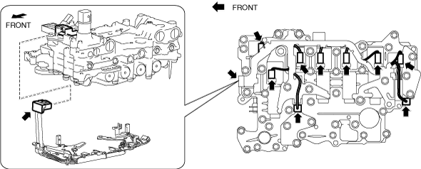
10. Disconnect the coupler component connectors.
-
Caution
-
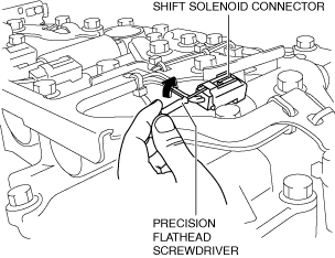
• Do not scratch the shift solenoid, shift solenoid connector, oil pressure switch, and oil pressure switch connector with the precision flathead screwdriver.
• When disconnecting connectors, grasp the connectors, not the wiring harnesses. Otherwise, the wiring harnesses may be pulled out of the connector causing poor contact.
- (1) Disconnect connector A and connector C by pressing the connector tab with your fingers.
-
- (2) Insert a precision flathead screwdriver and move it in the direction of the arrow to disconnect connector B as shown in the figure.
-
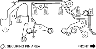
11. Remove the coupler component.
-
Caution
-
• Because there are solenoid valve securing pins in the areas circled with a dotted line shown in the figure. Always verify that the solenoid valve securing pins are on the control valve body when installing the coupler component.
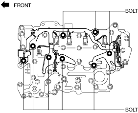
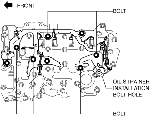
12. Temporarily install the coupler component so that the oil strainer installation bolt hole does not deviate.
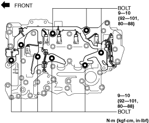
13. After verifying that the oil strainer installation bolt hole is not deviated, install the coupler component.
-
Caution
-
• After assembling the coupler component, verify that shift solenoids No.1, 2, 3, 4, the pressure control solenoid, and the TCC control solenoid cannot be pulled out from the control valve body.
14. Connect the coupler component connectors.
15. Install the control valve body. (See CONTROL VALVE BODY REMOVAL/INSTALLATION [EV6A-EL].)
16. Install the oil seal (control valve body). (See OIL SEAL (CONTROL VALVE BODY) REPLACEMENT [EV6A-EL].)
17. Install the hose clamp. (See CONTROL VALVE BODY REMOVAL/INSTALLATION [EV6A-EL].)
18. Connect the control valve body connector. (See CONTROL VALVE BODY REMOVAL/INSTALLATION [EV6A-EL].)
-
Caution
-
• Make sure that your hand does not touch the terminal as the connector terminal could be damaged.
• Verify that there is no fluid or foreign matter adhering to the connector before connecting the connector.
• Insert the connector straight as the connector terminal could be damaged.
• Rotate the connector lever until a click is heard.
19. Add the ATF. (See AUTOMATIC TRANSAXLE FLUID (ATF) REPLACEMENT [EV6A-EL].)
20. Install the front under cover No.2. (See FRONT UNDER COVER No.2 REMOVAL/INSTALLATION.)
21. Install the front under cover No.1. (See FRONT UNDER COVER No.1 REMOVAL/INSTALLATION.)
22. Install the following parts as a single unit. (See INTAKE-AIR SYSTEM REMOVAL/INSTALLATION [SKYACTIV-G (WITH CYLINDER DEACTIVATION (E))].)
-
• Air cleaner cover
• Air cleaner element
• Fresh-air duct
• Air cleaner case
• Air hose
• Resonance chamber
23. Connect the negative battery terminal. (See NEGATIVE BATTERY TERMINAL DISCONNECTION/CONNECTION [(E)].)
24. Perform the “Mechanical System Test”. (See MECHANICAL SYSTEM TEST [EV6A-EL].)