 |
am3zzw00034190
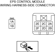
EPS CONTROL MODULE INSPECTION
id061300802400
1. Attach the tester lead to the underside of the EPS control module connector and inspect the voltage according to the terminal voltage table (reference).
Terminal Voltage Table (Reference)
am3zzw00034190
|
|
Terminal |
Signal name |
Connected to |
Measured item |
Measured terminal (measurement condition) |
Voltage (V) |
Inspection item(s) |
|---|---|---|---|---|---|---|
|
1A
|
Battery power supply
|
Battery
|
Voltage
|
Under any condition
|
B+
|
• Wiring harness (1A—battery)
• Fuse (F19 60A)
|
|
1B
|
Ground
|
Ground point
|
Voltage
|
Under any condition
|
Approx. 0
|
• Ground point
• Wiring harness (1B—ground point)
|
|
2A
|
CAN_L
|
—
|
Perform DTC inspection
|
—
|
||
|
2B
|
—
|
—
|
—
|
—
|
—
|
—
|
|
2C
|
CAN_H
|
—
|
Perform DTC inspection
|
—
|
||
|
2D
|
—
|
—
|
—
|
—
|
—
|
—
|
|
2E
|
—
|
—
|
—
|
—
|
—
|
—
|
|
2F
|
Ignition power supply
|
IG1 relay No.2
|
Voltage
|
Ignition ON (engine off or on)
|
B+
|
• Wiring harness (2F—IG1 relay No.2—battery)
• Fuse (F48 7.5A)
|
|
Ignition off
|
1 or less
|
|||||